2 layers90 × 44 mm
Nixie main
snakeye/nixie-clock
Nixie clock based on ESP32-C3 Super Mini module and Soviet IN-14 tubes
12 parts

 snakeye/nixie-clock
Nixie clock based on ESP32-C3 Super Mini module and Soviet IN-14 tubes
Nixie clock is an open-source printed circuit board by snakeye, from the snakeye/nixie-clock repository on GitHub. It is a 2-layer board of 90 × 44 mm with 22 parts on 46 nets, routed with 493 tracks and 9 vias.
It is built around the TLP627(F) and 74HC595. Its parts include 8 resistors, 6 ICs, 2 capacitors and 2 connectors. It belongs with the lEDs and displays boards and the ESP32 and RISC-V boards of this library.


An ESP32-C3 powered Nixie clock built around custom KiCad hardware and Arduino firmware.
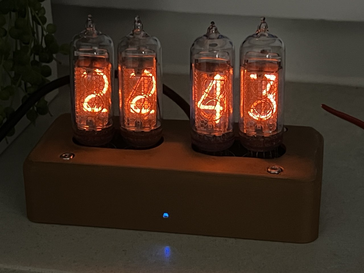
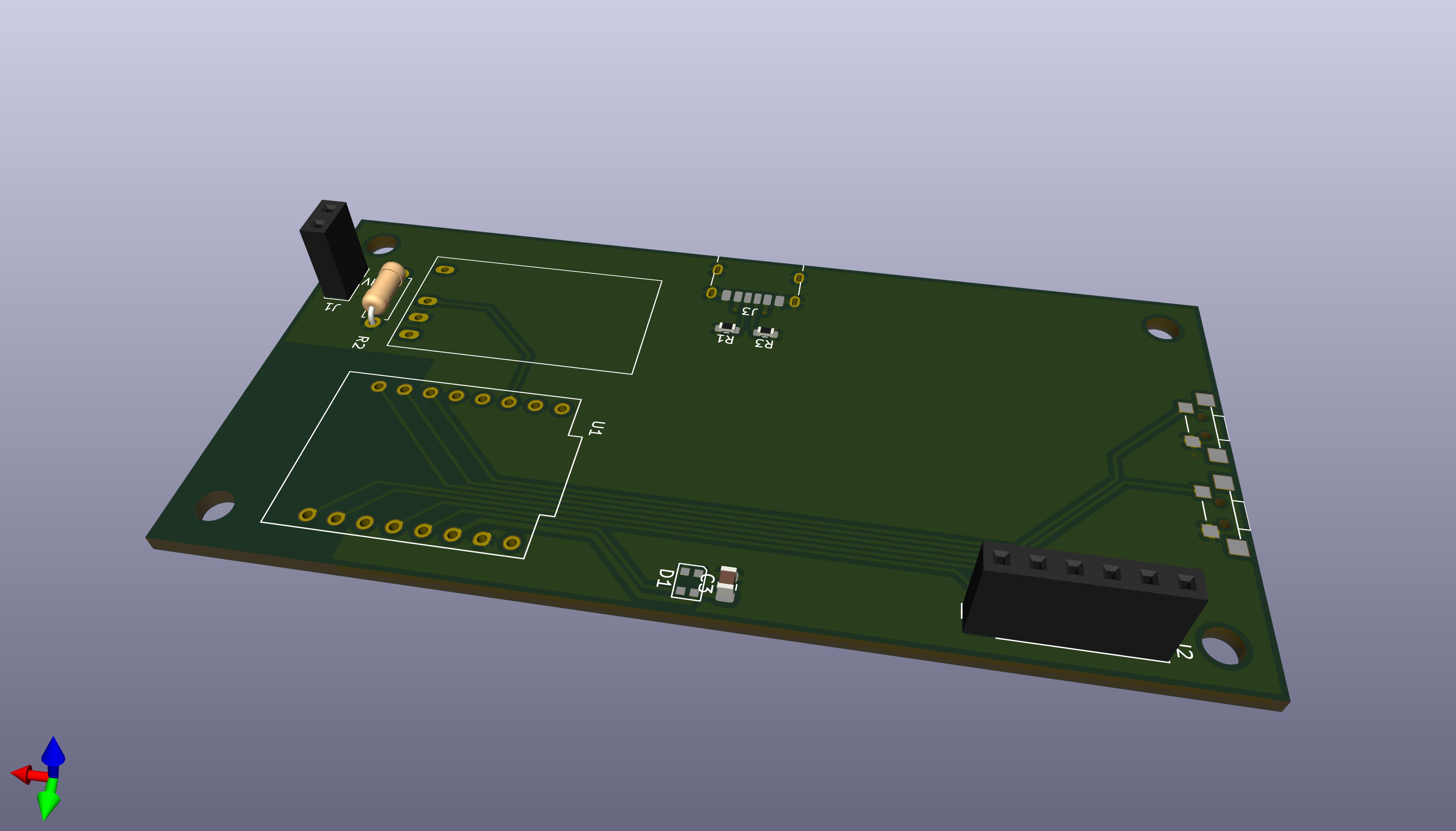
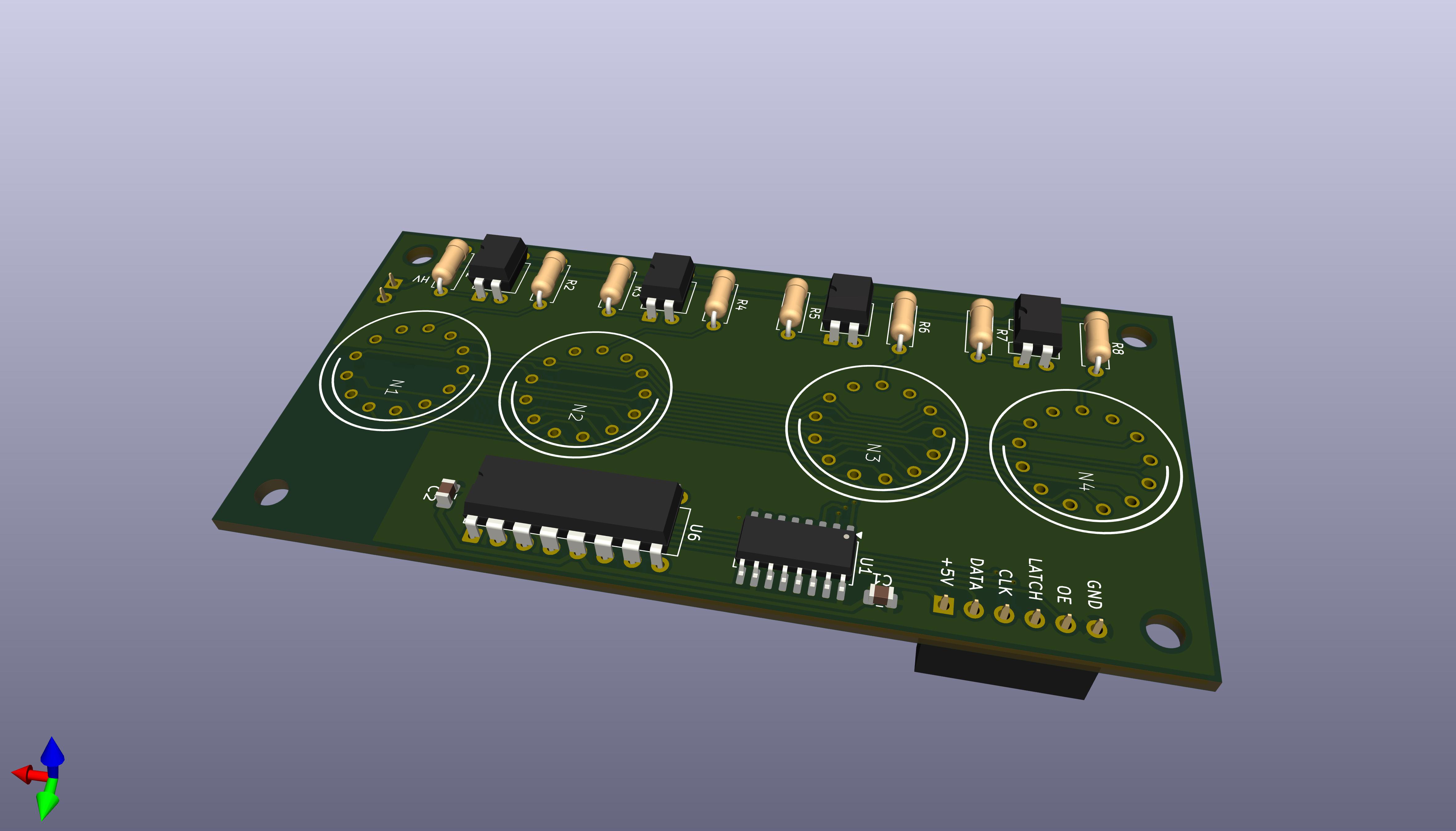
This repository contains the hardware and firmware for a four-digit Nixie clock. It uses Wi-Fi to sync time from NTP, drives the tubes with a multiplexed display stage, and keeps the high-voltage supply disabled until the clock has a valid time.
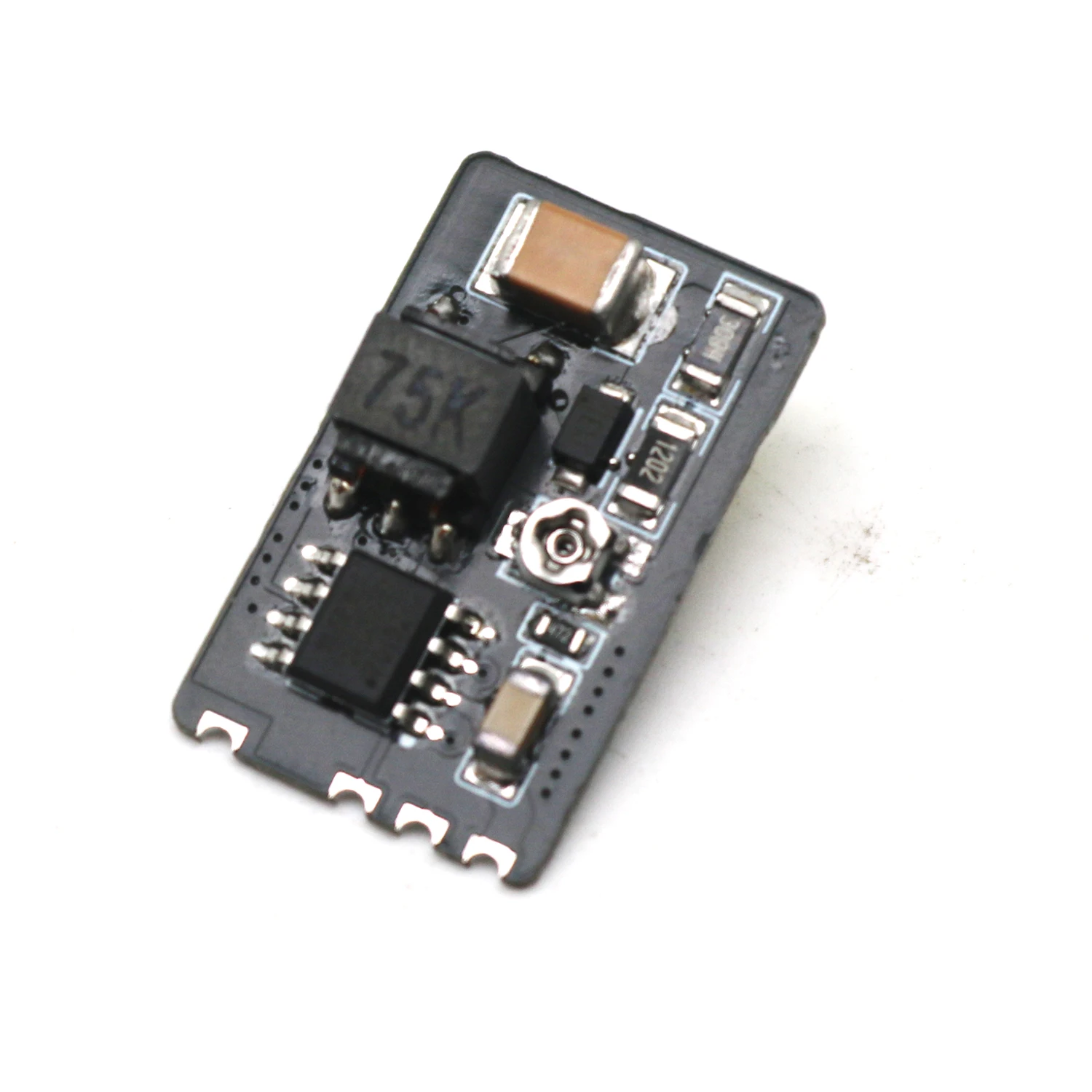
I've used this particular module found on AliExpress. It features voltage adjustment. Other modules should also work, but they'll require proper wiring.
The firmware boots in a safe state with the display blanked and the high-voltage rail off. After Wi-Fi connects and NTP provides a valid time, the clock enables the high-voltage section and starts showing the current time.
When a successful sync happens, the firmware opens a short OTA maintenance window. If an upload starts, the high-voltage rail is disabled while the update is in progress.
Button 1 has a long-press action that starts cathode cleaning manually. The same cleaning routine also runs automatically once per day when the clock reaches midnight.
firmware/ - PlatformIO project for the ESP32-C3hardware/main/ - main KiCad project for the clock boardhardware/indicators/ - indicator-board KiCad projectdocs/ - photos and other documentation assetsfirmware/ in PlatformIO or your preferred VS Code setup.firmware/src/config.h.example to firmware/src/config.h.esp32c3 environment.The firmware is configured for the esp32-c3-devkitm-1 board.
nixie-clock.firmware/src/config.h is ignored by Git so local Wi-Fi credentials stay machine-specific.| Qty | Value | Footprint | References |
|---|---|---|---|
| 4 | 22K | Resistor_THT:R_Axial_DIN0207_L6.3mm_D2.5mm_P7.62mm_Horizontal | R2, R4, R6, R8 |
| 4 | 390 | Resistor_THT:R_Axial_DIN0207_L6.3mm_D2.5mm_P7.62mm_Horizontal | R1, R3, R5, R7 |
| 4 | IN-14 | nixies-us:nixies-us-IN-14 | N1, N2, N3, N4 |
| 4 | TLP627 | Package_DIP:DIP-4_W7.62mm | U2, U3, U4, U5 |
| 2 | 0.1uF | Capacitor_SMD:C_0805_2012Metric | C1, C2 |
| 1 | 155ID1 | Package_DIP:DIP-16_W7.62mm | U6 |
| 1 | 74HC595 | Package_SO:SOP-16_4.4x10.4mm_P1.27mm | U1 |
| 1 | HV | Connector_PinSocket_2.54mm:PinSocket_1x02_P2.54mm_Vertical | J1 |
| 1 | MCU | Connector_PinSocket_2.54mm:PinSocket_1x06_P2.54mm_Vertical | J2 |
It measures 90 × 44 mm and has 2 copper layers, 1.6 mm thick.
22 parts, built around the TLP627(F) and 74HC595. The full list of its parts is on this page, with links to each part's symbol and footprint where PCBKit's library has them.
From the snakeye/nixie-clock repository on GitHub, at the commit this page was made from: the board is hardware/indicators/nixie-clock.kicad_pcb and its schematic hardware/indicators/nixie-clock.kicad_sch. PCBKit opens the board in the browser, with nothing to install.
Its repository states no licence, so its author keeps all rights: ask snakeye before reusing the design.
snakeye/nixie-clock
Nixie clock based on ESP32-C3 Super Mini module and Soviet IN-14 tubes

lambdaBoost/MC6205-graphical-display
graphical display on old neon plasma screen


taltalp/ESP32_nixieclock
Nixie-tube Clock using ESP32 KiCad PCB design and Arduino projects.

fablab-wue/piTelex.supplement
This project hold the additional files for the teletype project piTelex

carlos-paniagua/TapeTicsProject
This repository contains the hardware and software design files for TapeTics

joseguerra3000/current-loops
Diseno de Modulo de lazos de corriente para monitoreo de sensores tipo ON-OFF a largas distancias.

