
2 layers63 × 75 mm

 slimmsehli/RelayBoard
Relay Board for 250VAC/10VDC controlled by 5v
Relay board v2 is an open-source printed circuit board by slimmsehli, from the slimmsehli/RelayBoard repository on GitHub. It is a 2-layer board of 74.5 × 63 mm with 33 parts on 38 nets, routed with 146 tracks and 0 vias.
It is built around the BC817. Its parts include 8 resistors, 8 diodes, 5 connectors, 4 ICs and 4 transistors. It belongs with the home automation and IoT boards of this library.
🟢 4-Channel Relay Board with Opto-Isolation for Arduino/Raspberry Pi
This project is a modular, 4-channel relay control board designed for microcontrollers like **Arduino, Raspberry Pi, ESP32, etc. The board features opto-isolation for electrical protection and safety, and is ideal for home automation, IoT, or industrial control applications.
| Feature | Description |
|---|---|
| Relay type | 5V SPDT |
| Input voltage | 5V logic compatible |
| Isolation | Optical + PCB drilled spacing |
| Max switching | 10A 250V AC / 10A 30V DC |
| Board size | 65mmx70mm |
| Control headers | 4-pin input control (IN1–IN4) |
| Load terminals | NO, COM, NC per relay |
| Pin | Description |
|---|---|
| IN1 | Control for Relay 1 |
| IN2 | Control for Relay 2 |
| IN3 | Control for Relay 3 |
| IN4 | Control for Relay 4 |
| VCC | Input side power (5V) |
| GND | Ground |
Each control input drives one relay via an optocoupler for full isolation.
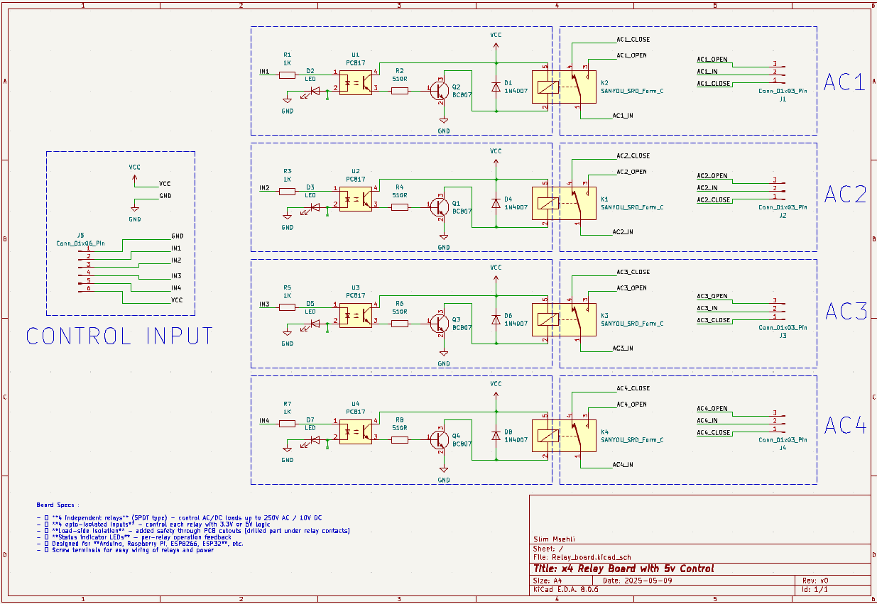
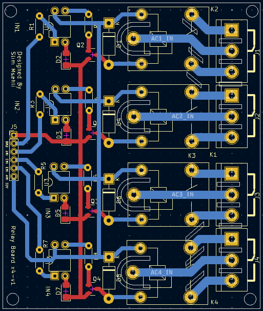
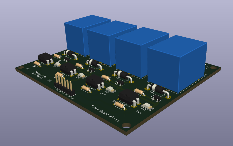
| Qty | Value | Footprint | References |
|---|---|---|---|
| 4 | 1K | Resistor_THT:R_Axial_DIN0207_L6.3mm_D2.5mm_P10.16mm_Horizontal | R1, R3, R5, R7 |
| 4 | 1N4007 | Diode_THT:D_DO-41_SOD81_P10.16mm_Horizontal | D1, D4, D6, D8 |
| 4 | 510R | Resistor_THT:R_Axial_DIN0207_L6.3mm_D2.5mm_P10.16mm_Horizontal | R2, R4, R6, R8 |
| 4 | BC817 | Package_TO_SOT_SMD:SOT-23 | Q1, Q2, Q3, Q4 |
| 4 | Conn_01x03_Pin | TerminalBlock:TerminalBlock_bornier-3_P5.08mm | J1, J2, J3, J4 |
| 4 | LED | LED_SMD:LED_1206_3216Metric_Pad1.42x1.75mm_HandSolder | D2, D3, D5, D7 |
| 4 | PC817 | Package_DIP:DIP-4_W7.62mm | U1, U2, U3, U4 |
| 4 | SANYOU_SRD_Form_C | Relay_THT:Relay_SPDT_SANYOU_SRD_Series_Form_C | K1, K2, K3, K4 |
| 1 | Conn_01x06_Pin | Connector_PinHeader_2.54mm:PinHeader_1x06_P2.54mm_Vertical | J5 |

W0rthlessS0ul/nRF24_jammer
The nRF24 jammer is a powerful tool that requires an ESP32 and configurable numbers of NRF24 modules to assemble.

Ardumower/ardumower
Develop an open source robotic lawn mower (HW+SW reference platform)

qbancoffee/imac_g3_ivad_board_init
iMac G3 IVAD board initialization with an arduino


BitDogLab/BitDogLab
Open-source educational hardware for embedded systems, programming, electronics, and physical computing.


It measures 74.5 × 63 mm and has 2 copper layers, 1.6 mm thick.
33 parts, built around the BC817. The full list of its parts is on this page, with links to each part's symbol and footprint where PCBKit's library has them.
From the slimmsehli/RelayBoard repository on GitHub, at the commit this page was made from: the board is Relay_board_kiCad_v2/Relay_board_v2.kicad_pcb and its schematic Relay_board/Relay_board/Relay_board.kicad_sch. PCBKit opens the board in the browser, with nothing to install.
Its repository states no licence, so its author keeps all rights: ask slimmsehli before reusing the design.