2 layers100 × 100 mm

 skiselev/ttl-clock28
74xx ICs Based Digital Clock
Ttl clock is an open-source printed circuit board by skiselev, from the skiselev/ttl-clock repository on GitHub, published under the GPL-3.0 licence. It is a 2-layer board of 100 × 100 mm with 64 parts on 162 nets, routed with 1,103 tracks and 30 vias.
It is built around the 74LS00SC, DA56-11SRWA and 74HCT4060D. Its parts include 19 capacitors, 19 ICs, 7 resistors, 4 diodes and 3 switches. It belongs with the lEDs and displays boards of this library.


74xx ICs Based Digital Clock
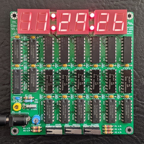
I got a bit tired from soldering SMD components, writing firmware, (and also observing people building vintage-looking Nixie clocks using modern microcontrollers). And recently when cleaning my parts boxes I found several 74LS47 7-segment decoders, some 74LS90 decade counters, and MAN1A 7-segment displays. So I thought, why not to build a nice little clock using these components.
Please refer to the schematic file in the Design Files section below.
The clock uses a 32768 Hz quartz crystal (X1) and 74HC4060 counter/divider IC (U1) to generate 2 Hz signal. This signal is divided further by 2 using a part of 74LS90 counter (U6). The obtained 1 Hz signal is fed to two 74LS90 counters (U11 and U12) that count seconds. The seconds reset circuit implemented using two 74LS00 NAND gates (U4A and U4B). This circuit resets both seconds and tens of seconds counters when they reach "60" or when "SECONDS" switch (SW1) is pressed, allowing seconds adjustment.
The most significant bit of tens of seconds counter is fed to the minutes counter implemented using two 74LS90 counters (U13 and U14) through a multiplexer built from three 74LS00 NAND gates (U2C, U2D, U4D). The multiplexer selects between this "one pulse per minute" signal and the 2 Hz signal allowing setting up minutes. Two additional 74LS00 NAND gates (U2A and U2B) implement an RS flip-flop used to de-bounce "MINUTES" switch (SW2). The tens of the minutes 74LS90 counter (U14) is wired so that it resets itself when it reaches count of "6", so that minutes wrap around at "60".
Similarly to minutes, the most significant bit of tens of minutes is fed to the hours counter implemented using two 74LS90 counters (U15 and U16) through a multiplexer built from three 74LS00 NAND gates (U3C, U3D, U4C). The multiplexer selects between this "one pulse per hour" signal and the 2 Hz signal allowing setting up hours. Two additional 74LS00 NAND gates (U3A and U3B) implement an RS flip-flop used to de-bounce "HOURS" switch (SW3). Both hours counters are wired in such a way that they will reset themselves once they reach the count of "24".
Six 74LS47 7-segment decoders (U5 - U10) are used to decode the binary outputs of the counters and 7-segment displays (U17 - U19) display the result in human readable 24-hours time format.
TTL Clock V1.1 project on Mouser.com - View and order all components except of the PCB.
TTL Clock Version 1.1 project on OSH Park - Order PCBs.
| Component type | Reference | Description | Quantity | Possible sources and notes |
|---|---|---|---|---|
| PCB | TTL Clock V1.1 Printed Circuit Board | 1 | Order from OSH Park or another PCB manufacturer using provided KiCad or Gerber files | |
| Stand | 3D printed stand for the clock | 1 | (Optional) Print on a 3D printer using stand.stl. Thanks to Michael K. for designing this stand. | |
| Screw | M3 x 6mm screw | 2 | (Optional) | |
| Capacitor | C1 - C16 | 0.1uF, 50V, multilayer ceramic capacitor, axial | 16 | Mouser: 594-A104K15X7RF5UAA |
| Capacitor | C17 | 100uF, 25V, electrolytic capacitor, radial, 6.3 mm diameter | 1 | Mouser: 710-860040473003 |
| Capacitor | C18 | 12pF, 50V, multilayer ceramic capacitor, 5.08 mm lead spacing | 1 | Mouser: 810-FK28C0G1H120J |
| Trimmer Capacitor | C19 | 5-30pF, trimmer capacitor, 5 mm lead spacing | 1 | Mouser: 659-GKG20015 |
| LED | D1 - D4 | 3 mm LED, same color as U17 - U19 | 4 | Mouser: 859-LTL-4221 (red, 623 nm) 859-LTL-4211 (red, 697 nm, 2.5 mcd), 859-LTL-4231 (green, 565 nm) |
| Connector | P1 | DC Power Jack | 1 | Mouser: 806-KLDX-0202-A |
| Resistor | R1 - R5 | 4.7 kOhm, 1/4 W | 5 | Mouser: 588-OK4725E-R52, 603-MFR25SFRF52-4K7 |
| Resistor | R6 | 330 kOhm, 1/4 W | 1 | Mouser: 588-OK3345E-R52 |
| Resistor | R7 | 15 MOhm, 1/4 W | 1 | Mouser: 660-CF1/4C156J |
| Resistor Array | RR1 - RR6 | 470 Ohm, 8 isolated resistors, 16 pin DIP | 6 | Mouser: 652-4116R-1LF-470, 652-4116R-1-470, or 46 x 470 ohm discrete resistors |
| Switch | SW1 - SW3 | SPDT momentary switch, Omron D2F | 3 | Mouser: 612-SS0750301F040P1A, 653-D2F-01L |
| Integrated Circuit | U1 | 14-stage binary counter with oscillator, 74HC4060 | 1 | Mouser: 595-SN74HC4060N, 595-CD74HCT4060E, 595-CD74HC4060E |
| Integrated Circuit | U2 - U4 | Quad 4-input NAND gate, 74LS00 | 3 | Mouser: 595-SN74LS00N, 595-SN74LS00NE4 |
| Integrated Circuit | U5 - U10 | BCD to 7-segment decoder, 74LS47 or 74LS247 | 6 | Mouser: 595-SN74LS47N, 595-SN74LS47NE4, 595-SN74LS247N, 595-SN74LS247NE4 |
| Integrated Circuit | U11 - U16 | Decade counter, 74LS90 | 6 | Mouser: 595-SN74LS90N, 595-SN74LS90NE4 |
| LED Display | U17 - U19 | 7-segment LED display, 2 digits, common anode | 3 | Mouser: 859-LTD-6910HR (red, 623 nm), 859-LTD-6410G (green, 569 nm) |
| Crystal Resonator | X1 | 32768 Hz, 12.5pF load capacitance, tuning fork | 1 | Mouser: 695-CFS-20632768EZBB, 815-AB26T-32.768KHZ |
| Power Supply | 5 V, 550 mA | 1 | Mouser: 490-SWI3-5-N-P5 (US plug), 490-SWI3-5-E-P5 (EU plug) |
| Qty | Value | Footprint | References |
|---|---|---|---|
| 16 | 100nF | My_Components:Cap_Cer_762 | C1, C2, C3, C4, C5, C6, C7, C8, C9, C10, C11, C12, C13, C14, C15, C16 |
| 6 | 470 | My_Components:IC_DIP16_300 | RP1, RP2, RP3, RP4, RP5, RP6 |
| 6 | 74LS47 | My_Components:IC_DIP16_300 | U5, U6, U7, U8, U9, U10 |
| 6 | 74LS90 | My_Components:IC_DIP14_300 | U11, U12, U13, U14, U15, U16 |
| 5 | 4.7k | My_Components:Res_762 | R1, R2, R3, R4, R5 |
| 4 | CONN_1 | MountingHole:MountingHole_3mm_Pad_Via | HOLE1, HOLE2, HOLE3, HOLE4 |
| 4 | LED | LED_THT:LED_D3.0mm_FlatTop | D1, D2, D3, D4 |
| 3 | 74LS00 | My_Components:IC_DIP14_300 | U2, U3, U4 |
| 3 | DA56-11SRWA | Display_7Segment:DA56-11SURKWA | U17, U18, U19 |
| 1 | 100uF | Capacitor_THT:CP_Radial_D6.3mm_P2.50mm | C17 |
| 1 | 12pF | My_Components:Cap_Cer_508 | C18 |
| 1 | 15M | My_Components:Res_762 | R7 |
| 1 | 32768Hz | My_Components:Crystal_32K_Horiz | Y1 |
| 1 | 330k | My_Components:Res_762 | R6 |
| 1 | 5-30pF | My_Components:C_Trim_Murata | C19 |
| 1 | 5V | My_Components:Conn_Power_Jack_Circular_Pads | P1 |
| 1 | 74HCT4060 | My_Components:IC_DIP16_300 | U1 |
| 1 | HOURS | My_Components:Switch_SPDP_D2F | SW3 |
| 1 | MINUTES | My_Components:Switch_SPDP_D2F | SW2 |
| 1 | SECONDS | My_Components:Switch_SPDP_D2F | SW1 |
It measures 100 × 100 mm and has 2 copper layers, 1.6 mm thick.
64 parts, built around the 74LS00SC, DA56-11SRWA and 74HCT4060D. The full list of its parts is on this page, with links to each part's symbol and footprint where PCBKit's library has them.
From the skiselev/ttl-clock repository on GitHub, at the commit this page was made from: the board is KiCad/ttl_clock.kicad_pcb. PCBKit opens the board in the browser, with nothing to install.
Its repository publishes it under the GPL-3.0 licence: you may reuse it on that licence's terms (keep the author's notice, and for a copyleft licence share your changes alike).


jes/scamp-cpu
A homebrew 16-bit CPU with a homebrew Unix-like-ish operating system.

mudmin/AnotherMaker
This is where I will store code snippets for AnotherMaker Videos


Nakazoto/CenturionComputer
This is just a simple backup of all the files related to the Centurion that I have stored on my HD. The Wiki itself has far more in-depth information about the Centurion and it's individual cards.

The-Invent0r/8-bit-Computer-PCB
These are the KiCAD files for my 8-Bit Computer.

tjboldt/Apple2-IO-RPi
Apple II expansion card using a Raspberry Pi for I/O