2 layers60 × 30 mm
Controller
google/mozc-devices
Circuit diagrams and firmware source code for Gboard DIY keyboards
11 parts3kApache-2.0

 skiselev/ps2-xt11
PS/2 to XT Keyboard Converter
Ps2-xt is an open-source printed circuit board by skiselev, from the skiselev/ps2-xt repository on GitHub, published under the CERN-OHL-S-2.0 licence. It is a 2-layer board of 23.5 × 48.9 mm with 11 parts on 12 nets, routed with 67 tracks and 0 vias.
Its parts include 3 resistors, 2 connectors, 1 capacitor, 1 IC and 1 diode. It belongs with the keyboards and input boards and the PIC boards of this library.
PS/2 to XT Keyboard Converter
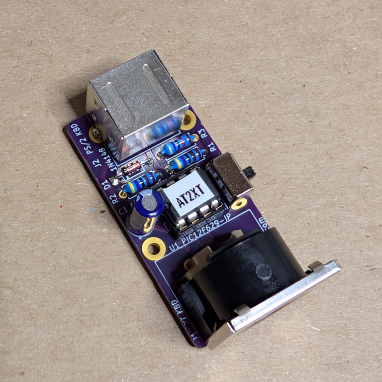
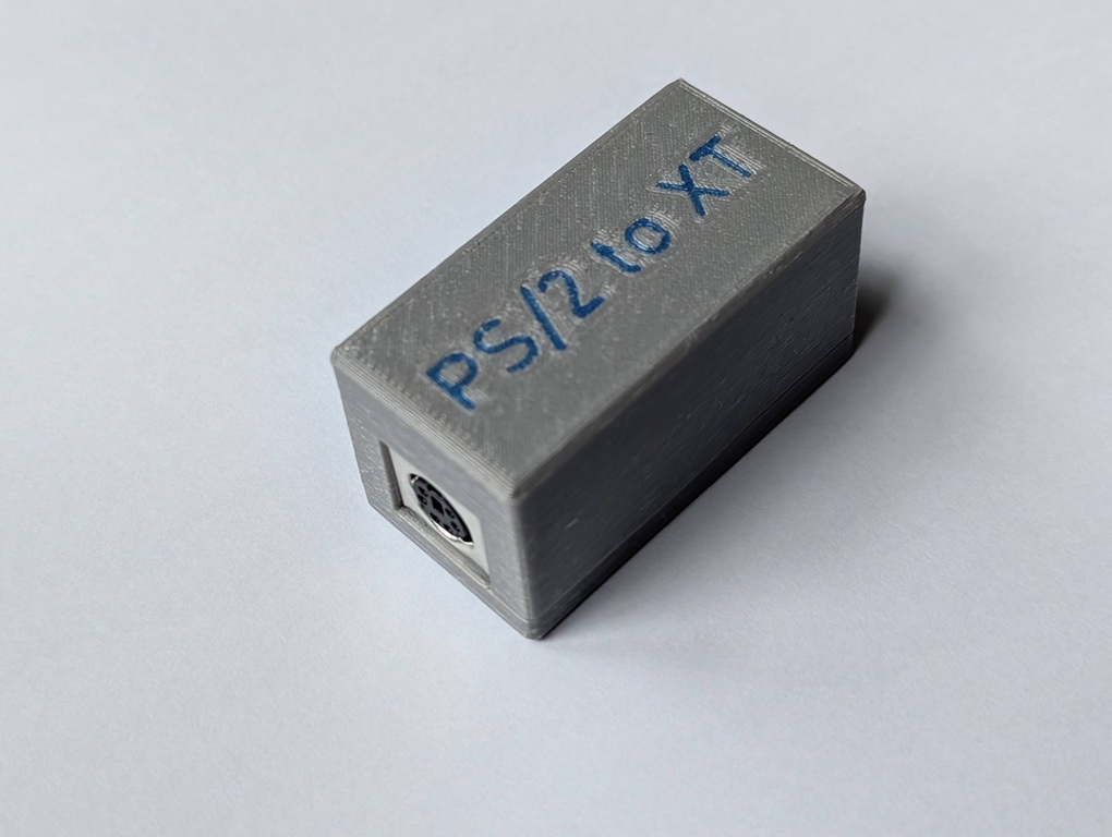
The PS/2 to XT project is yet another PCB design for the AT2XT keyboard converter developed by Vintage Computer Federation community.
It allows connecting a PS/2 keyboard to an IBM PC, IBM XT, or compatibles. An AT keyboard with an additional passive AT to PS/2 adapter, or a USB keyboard that also supports AT protocol using passive USB to PS/2 adapter, can be also used with this converter.
It was designed for several reasons:
| Component type | Reference | Description | Quantity | Possible sources and notes |
|---|---|---|---|---|
| PCB | PS2-XT PCB - Version 1.0 | 1 | Order from a PCB manufacturer of your choice using provided Gerber or KiCad files | |
| Integrated Circuit | U1 | PIC12F629 Microcontroller RTC, 8 pin DIP | 1 | Mouser 579-PIC12F629IP |
| IC Socket | U2 | 8 pin DIP | 1 | Mouser 737-ICS-308-T |
| Diode | D1 | 1N4148 | 1 | Mouser 512-1N4148TA |
| Capacitor | C1 | 47 pF, 25V, electrolythic, 2 mm pitch | 1 | Mouser 710-860040472001 |
| Resistor | R1 - R2 | 4.7 kohm, 0.25 W, 1% tolerance, axial | 2 | Mouser 603-MFR-25FRF52-4K7 |
| Resistor | R3 | 47 kohm, 0.25 W, 1% tolerance, axial | 1 | Mouser 603-MFR-25FRF52-47K |
| Connector | J1 | DIN-5 socket | 1 | Mouser 806-KCDX-5S-S2 |
| Connector | J2 | MiniDin-6 socket | 1 | Mouser 806-KMDGX-6S-BS |
| Switch | SW1 | Slider SPDT switch | 1 | Mouser 179-SLW8645872ARAND |
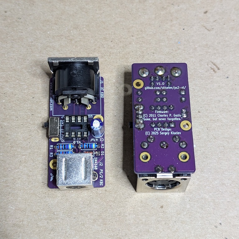
The hardware design itself, including schematic, PCB layout design, and 3D printed case design files are licensed under the strongly-reciprocal variant of CERN Open Hardware Licence version 2. Documentation, including this file, is licensed under the Creative Commons Attribution-ShareAlike 4.0 International License.
| Qty | Value | Footprint | References |
|---|---|---|---|
| 2 | 4.7k | Resistor_THT:R_Axial_DIN0207_L6.3mm_D2.5mm_P7.62mm_Horizontal | R1, R2 |
| 2 | M2 | MountingHole:MountingHole_2.2mm_M2_Pad | H1, H2 |
| 1 | 1N4148 | Diode_THT:D_DO-35_SOD27_P7.62mm_Horizontal | D1 |
| 1 | 47k | Resistor_THT:R_Axial_DIN0207_L6.3mm_D2.5mm_P7.62mm_Horizontal | R3 |
| 1 | 47uF | Capacitor_THT:CP_Radial_D5.0mm_P2.00mm | C1 |
| 1 | E0 PASS | Button_Switch_THT:SW_CuK_OS102011MA1QN1_SPDT_Angled | SW1 |
| 1 | PIC12F629-IP | Package_DIP:DIP-8_W7.62mm | U1 |
| 1 | PS/2 KBD | My_Components:Conn_Mini_DIN_6pin | J2 |
| 1 | XT KBD | My_Components:Conn_DIN_5pin | J1 |
It measures 23.5 × 48.9 mm and has 2 copper layers, 1.6 mm thick.
11 parts. The full list of its parts is on this page, with links to each part's symbol and footprint where PCBKit's library has them.
From the skiselev/ps2-xt repository on GitHub, at the commit this page was made from: the board is KiCad/ps2-xt.kicad_pcb and its schematic KiCad/ps2-xt.kicad_sch. PCBKit opens the board in the browser, with nothing to install.
Its repository publishes it under the CERN-OHL-S-2.0 licence: you may reuse it on that licence's terms (keep the author's notice, and for a copyleft licence share your changes alike).
google/mozc-devices
Circuit diagrams and firmware source code for Gboard DIY keyboards


FrameworkComputer/ExpansionCards
Reference designs and documentation to create Expansion Cards for the Framework Laptop

hoglet67/RGBtoHDMI
Bare-metal Raspberry Pi project that provides pixel-perfect sampling of Retro Computer RGB/YUV video and conversion to HDMI

hackclub/OnBoard
💡 Join 1,000 teenagers and make your first PCB with a $100 grant!


tardate/LittleArduinoProjects
a collection of "Little Electronic & Arduino Projects", most involving electronics or an Arduino in one way or another!

basilfx/TRADFRI-Hacking
Hacking IKEA TRÅDFRI products, such as light bulbs, window blinds and other accessories.