2 layers125 × 98 mm
3-in-1
mudmin/AnotherMaker
This is where I will store code snippets for AnotherMaker Videos
44 parts258

 skiselev/monster-fdc78
ISA floppy disk controller card that supports up to 8 floppy drives
Isa monster fdc is an open-source printed circuit board by skiselev, from the skiselev/monster-fdc repository on GitHub. It is a 2-layer board of 139.7 × 101.6 mm with 57 parts on 211 nets, routed with 2,758 tracks and 148 vias.
It is built around the GD75232N, 74AHCT138D and 74HCT688D. Its parts include 22 capacitors, 10 ICs, 5 connectors and 2 crystals.


ISA floppy disk controller card that supports up to 8 floppy drives
Monster FDC is an ISA floppy disk controller card that features two FDCs. Each FDC supports up to four floppy drives. IRQ and DMA channel are configurable for the secondary FDC, and they are hardwired to IRQ6 and DMA2 for the primary FDC. The card also includes a serial port (UART) with configurable I/O address and IRQ.
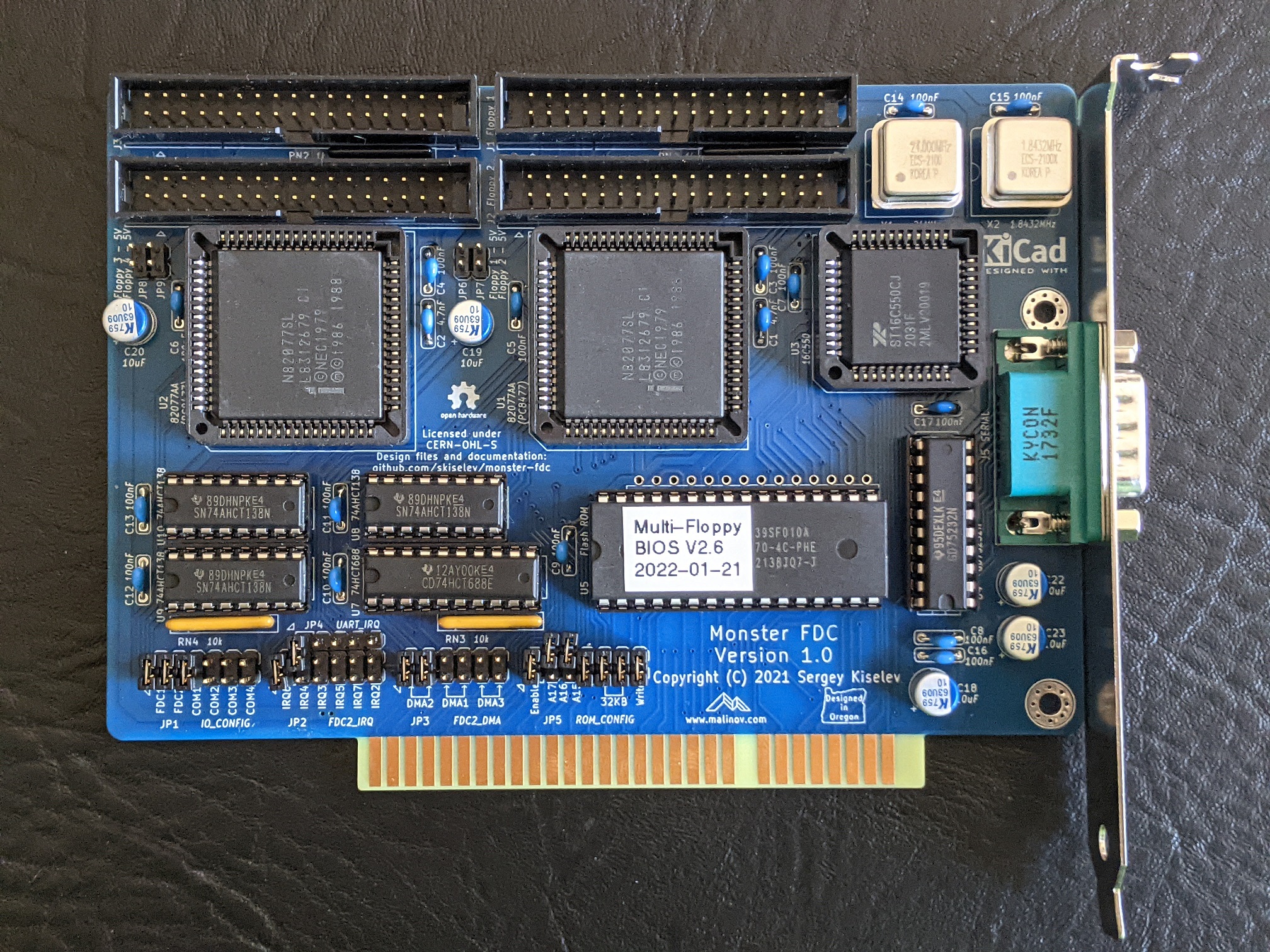
Monster FDC project on Mouser.com - View and order all components except of the PCB and the FDC ICs. Note that this BOM includes multiple alternatives for some parts (for example, for 2x17 pin floppy disk connector). Make sure to refer to the BOM below to order the right number of components.
Monster FDC project on Tindie: Complete Board; Monster FDC PCB.
| Component type | Reference | Description | Quantity | Possible sources and notes |
|---|---|---|---|---|
| PCB | Monster PCB - Version 1.0 | 1 | Buy from my Tindie store: Monster FDC PCB, or order from a PCB manufacturer of your choice using provided Gerber or KiCad files. It is recommended to use hard gold plating on the card edge connector. ENIG finish might work, but it is not as reliable. Definitely DO NOT use HASL finish on card edge connector. | |
| Integrated Circuit | U1, U2 | Intel 82077AA FDC, 68 pin PLCC | 2 | eBay; Possible replacements: National Semiconductor PC8477BV-1 or PC8477AV-1, Intel 82077SL, Intel 82077AA with various suffixes |
| Integrated Circuit | U3 | 16C550 UART, 44 pin PLCC | 1 | Mouser 701-ST16C550CJ44-F |
| Integrated Circuit | U4 | GD75232N RS-232 Transceivers, 20 pin DIP | 1 | Mouser 595-GD75232N |
| Integrated Circuit | U5 | SST39SF010A - 128 KiB Flash ROM, 32 pin DIP | 1* | Mouser 804-39SF010A7CPHE; Possible replacements: 128 KiB, 256 KiB, or 512 KiB 5V only Flash ROMs from other vendors. Note: Install either U5 or U6. It is recommended to install U5 |
| Integrated Circuit | U6 | 28C256 32 KiB or 28C64 8 KiB EEPROM, 28 pin DIP | 1* | Mouser 556-AT28C25615PU, 556-AT28C64B15PU. Note: Install either U5 or U6. It is recommended to install U5 |
| Integrated Circuit | U7 | CD74HCT688E Magnitude Comparator, 20 pin DIP | 1 | Mouser 595-CD74HCT688E |
| Integrated Circuit | U8 - U10 | SN74AHCT138N 3-to-8 Decoder, 16 pin DIP | 3 | Mouser 595-SN74AHCT138N |
| Crystal Oscillator | X1 | 24 MHz, 4 pin DIP, Half Can | 1 | Mouser 520-TCH2400 |
| Crystal Oscillator | X2 | 1.8432 MHz, 4 pin DIP, Half Can | 1 | Mouser 520-TCH184-X |
| Connector | J1 - J4 | 2x17 pin shrouded header, 2.54 mm pitch, vertical | 4 | Mouser 517-30334-6002 |
| Connector | J5 | DE-9 D-Sub connector, male, right angle | 1 | Mouser 806-K22X-E9P-N-99 |
| Pin Header | JP1 - JP3 | 2x6 pin header, 2.54 mm pitch, vertical | 3 | Mouser 649-67996-112HLF |
| Pin Header | JP4 | 1x5 pin header, 2.54 mm pitch, vertical | 1 | Mouser 649-68000-205HLF |
| Pin Header | JP5 | 2x7 pin header, 2.54 mm pitch, vertical | 1 | Mouser 649-67996-114HLF |
| Pin Header | JP6 - JP9 | 2x2 pin header, 2.54 mm pitch, vertical | 2* | Mouser 649-67996-104HLF. Note: Do not install unless using PS/2 floppy drives that are powered by pin 3 |
| Capacitor | C1, C2 | 4.7 nF, 50V, MLCC, 5 mm pitch | 2* | Mouser 810-FG28X7R1H472KNT0. Note: Optional, only required when using Intel 82077AA FDC |
| Capacitor | C3 - C17 | 100 nF, 50V, MLCC, 5 mm pitch | 15 | Mouser 810-FG28X7R1H104KNT6 |
| Capacitor | C18 - C23 | 10 uF, 63V, Organic Polymer, 6.3 mm diameter, 2.5 mm pitch | 5 | Mouser 80-A759EA106M1JAAE60 |
| Resistor Array | RN1, RN2 | 1 kohm, bussed, 6 pin SIP | 2 | Mouser 652-4606X-1LF-1K |
| Resistor Array | RN3, RN4 | 10 kohm, bussed, 6 pin SIP | 2 | Mouser 652-4606X-1LF-10K |
| IC Socket | U1, U2 | 68 pin PLCC, through hole | 2 | Mouser 517-8468-11B1-RK-TP |
| IC Socket | U3 | 44 pin PLCC, through hole | 1 | Mouser 517-8444-11B1-RK-TP |
| IC Socket | U4, U7 | 20 pin DIP | 2 | Mouser 649-DILB20P-223TLF |
| IC Socket | U5 | 32 pin DIP | 1* | Mouser 649-DILB32P223TLF. Note: Install either U5 or U6. It is recommended to install U5 |
| IC Socket | U6 | 28 pin DIP | 1* | Mouser 649-DILB28P223TLF. Note: Install either U5 or U6. It is recommended to install U5 |
| IC Socket | U8 - U10 | 16 pin DIP | 1 | Mouser 649-DILB16P-223TLF |
| Oscillator Socket | X1, X2 | 4 pin DIP, Half Can | 2 | Mouser 535-1108800 |
| Jumper | JP1 - JP5 | Shunt, 2 pin 2.54 mm pitch | 13 | Mouser 806-SX1100-B |
| Computer Bracket | Keystone Electronics 9200-1 Bracket with DE-9 cut-out | 1 | Mouser 534-9200-1, or a 3D printed bracket. Note: Use when serial port components are populated | |
| Screw | 4-40 Hex screw for D-Sub Connector | 2 | Mouser 806-JSX-1000. Note: Use when serial port components are populated | |
| Computer Bracket | Keystone Electronics 9202 ISA Bracket | 1 | Mouser 534-9202. Note: Use when serial port components are not populated | |
| Screw | 4-40 / 1/4" screw (for attaching ISA Bracket to the board) | 2 | Mouser 534-9900. Note: Use when serial port components are not populated |
The card can be built with some or all of the following devices and functionality:
The table below provides the list of components that are required for each one of the devices
| Device/Functionality | Components |
|---|---|
| Primary FDC Controller | U1, U8, U9, X1, J1, J2, JP1, JP6**, JP7**, C1*, C3, C5, C11, C12, C14, C19, RN1, RN4 |
| Secondary FDC Controller | U2, U8, U10, X1, J3, J4, JP1, JP2, JP3, JP8**, JP9**, C2*, C4, C6, C11, C13, C14, C20, RN2, RN4 |
| Serial port / UART | U3, U4, U8, U9, X2, J5, JP1, JP2, JP4, C7, C8, C11, C12, C15, C16, C17, C22, C23, RN4 |
| BIOS extension ROM | U5***, U6***, U7, JP5, RN3, C9, C10 |
| Shared components | C18 |
Notes:
None, so far
Monster FDC is an open source hardware project certified by Open Source Hardware Association, certification UID is US002072. The hardware design itself, including schematic and PCB layout design files are licensed under the strongly-reciprocal variant of CERN Open Hardware Licence version 2. The Multi-Flopppy BIOS code is licensed under GNU General Public License v3. Documentation, including this file, is licensed under the Creative Commons Attribution-ShareAlike 4.0 International License.
| Qty | Value | Footprint | References |
|---|---|---|---|
| 15 | 100nF | My_Components:Cap_Cer_508 | C3, C4, C5, C6, C7, C8, C9, C10, C11, C12, C13, C14, C15, C16, C17 |
| 5 | 10uF | My_Components:Cap_Elec_Radial_6.3mm | C18, C19, C20, C22, C23 |
| 3 | 74AHCT138 | My_Components:IC_DIP16_300 | U8, U9, U10 |
| 2 | 10k | My_Components:Conn_SIL6 | RN3, RN4 |
| 2 | 1k | My_Components:Conn_SIL6 | RN1, RN2 |
| 2 | 4.7nF | My_Components:Cap_Cer_508 | C1, C2 |
| 2 | 82077AA | My_Components:IC_PLCC68_TH | U1, U2 |
| 2 | HOLE | MountingHole:MountingHole_3.2mm_M3_Pad_Via | HOLE1, HOLE2 |
| 1 | 1.8432MHz | My_Components:OSC_Half_Can_DIP8 | X2 |
| 1 | 16C550 | My_Components:IC_PLCC44_TH | U3 |
| 1 | 24MHz | My_Components:OSC_Half_Can_DIP8 | X1 |
| 1 | 74HCT688 | My_Components:IC_DIP20_300 | U7 |
| 1 | BUSPC_DEV | My_Components:Conn_Edge_PCB_ISA8 | BUS1 |
| 1 | EEPROM | My_Components:IC_DIP28_600 | U6 |
| 1 | FDC2_DMA | My_Components:Conn_Pin_Header_6x2_2.54mm | JP3 |
| 1 | FDC2_IRQ | My_Components:Conn_Pin_Header_6x2_2.54mm | JP2 |
| 1 | Flash ROM | My_Components:IC_DIP32_600 | U5 |
| 1 | Floppy 1 | My_Components:Conn_Pin_Header_17x2_2.54mm_Shrouded | J1 |
| 1 | Floppy 1 - 5V | My_Components:Conn_Pin_Header_2x1_2.54mm_NoKey | JP6 |
| 1 | Floppy 2 | My_Components:Conn_Pin_Header_17x2_2.54mm_Shrouded | J2 |
| 1 | Floppy 2 - 5V | My_Components:Conn_Pin_Header_2x1_2.54mm_NoKey | JP7 |
| 1 | Floppy 3 | My_Components:Conn_Pin_Header_17x2_2.54mm_Shrouded | J3 |
| 1 | Floppy 3 - 5V | My_Components:Conn_Pin_Header_2x1_2.54mm_NoKey | JP8 |
| 1 | Floppy 4 | My_Components:Conn_Pin_Header_17x2_2.54mm_Shrouded | J4 |
| 1 | Floppy 4 - 5V | My_Components:Conn_Pin_Header_2x1_2.54mm_NoKey | JP9 |
| 1 | GD75232N | My_Components:IC_DIP20_300 | U4 |
| 1 | IO_CONFIG | My_Components:Conn_Pin_Header_6x2_2.54mm | JP1 |
| 1 | ROM_CONFIG | My_Components:Conn_Pin_Header_7x2_2.54mm | JP5 |
| 1 | SERIAL | My_Components:Conn_Dsub_DE9M | J5 |
| 1 | UART_IRQ | My_Components:Conn_Pin_Header_5x1_2.54mm | JP4 |
The 55 most common of 57 parts.
It measures 139.7 × 101.6 mm and has 2 copper layers, 1.6 mm thick.
57 parts, built around the GD75232N, 74AHCT138D and 74HCT688D. The full list of its parts is on this page, with links to each part's symbol and footprint where PCBKit's library has them.
From the skiselev/monster-fdc repository on GitHub, at the commit this page was made from: the board is KiCad/isa_monster_fdc.kicad_pcb. PCBKit opens the board in the browser, with nothing to install.
Its repository states no licence, so its author keeps all rights: ask skiselev before reusing the design.
mudmin/AnotherMaker
This is where I will store code snippets for AnotherMaker Videos


hkzlab/ISA_QuadUART2
This 8-bit ISA board will provide 4 serial RS232 ports using a single 16C554 controller. 2 ports are exposed on an external bracket and 2 are on internal headers.


