
2 layers65 × 56 mm

 skiselev/max7_proto10
Prototyping Board for Altera MAX7000 CPLDs
Max7 proto is an open-source printed circuit board by skiselev, from the skiselev/max7_proto repository on GitHub, published under the GPL-3.0 licence. It is a 2-layer board of 20.3 × 52.1 mm with 23 parts on 46 nets, routed with 316 tracks and 17 vias.
It is built around the EPM7064AETC44-7. Its parts include 9 capacitors, 5 resistors, 3 connectors, 2 ICs and 1 diode. It belongs with the fPGA and programmable logic boards and the FPGA and CPLD boards of this library.
Prototyping Board for Altera MAX7000 CPLDs
MAX7 Proto is a prototyping board based on Altera MAX7000 series CPLDs. The board has pin headers on both sides, and it can be easily mounted on a breadboard. It also includes a 3.3V LDO, so that MAX7000AE CPLDs can be used. A DIP-8 oscillator socket is provided for the designs that requre a clock.
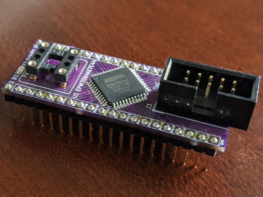
| Pin | Signal Name | Description | Pin | Signal Name | Description |
|---|---|---|---|---|---|
| J1-1 | VCC | Power Supply - +5V | J2-1 | VCC | Power Supply - +5V |
| J1-2 | PIN1_TDI | CPLD Pin 1; JTAG TDI; I/O | J2-2 | PIN44 | CPLD Pin 44; I/O |
| J1-3 | PIN2 | CPLD Pin 2; I/O | J2-3 | PIN43 | CPLD Pin 43; I/O |
| J1-4 | PIN3 | CPLD Pin 3; I/O | J2-4 | PIN42 | CPLD Pin 42; I/O |
| J1-5 | PIN5 | CPLD Pin 5; I/O | J2-5 | PIN40 | CPLD Pin 40; In, OE2, GCLK2 |
| J1-6 | PIN6 | CPLD Pin 6; I/O | J2-6 | PIN39 | CPLD Pin 39; In, GCLRn |
| J1-7 | PIN7_TMS | CPLD Pin 7; JTAG TMS; I/O | J2-7 | PIN38 | CPLD Pin 38; In, OE1n |
| J1-8 | PIN8 | CPLD Pin 8; I/O | J2-8 | PIN37 | CPLD Pin 37; In, GCLK2 |
| J1-9 | PIN10 | CPLD Pin 10; I/O | J2-9 | PIN35 | CPLD Pin 35; I/O |
| J1-10 | PIN11 | CPLD Pin 11; I/O | J2-10 | PIN34 | CPLD Pin 34; I/O |
| J1-11 | PIN12 | CPLD Pin 12; I/O | J2-11 | PIN33 | CPLD Pin 33; I/O |
| J1-12 | PIN13 | CPLD Pin 13; I/O | J2-12 | PIN32_TDO | CPLD Pin 32; JTAG TDO; I/O |
| J1-13 | PIN14 | CPLD Pin 14; I/O | J2-13 | PIN31 | CPLD Pin 31; I/O |
| J1-14 | PIN15 | CPLD Pin 15; I/O | J2-14 | PIN30 | CPLD Pin 30; I/O |
| J1-15 | PIN18 | CPLD Pin 18; I/O | J2-15 | PIN28 | CPLD Pin 28; I/O |
| J1-16 | PIN19 | CPLD Pin 19; I/O | J2-16 | PIN27 | CPLD Pin 27; I/O |
| J1-17 | PIN20 | CPLD Pin 20; I/O | J2-17 | PIN26_TCK | CPLD Pin 26; JTAG TCK; I/O |
| J1-18 | PIN21 | CPLD Pin 21; I/O | J2-18 | PIN25 | CPLD Pin 25; I/O |
| J1-19 | PIN22 | CPLD Pin 22; I/O | J2-19 | PIN23 | CPLD Pin 23; I/O |
| J1-20 | GND | Ground | J2-20 | GND | Ground |
| Pin | Signal Name | Description | Pin | Signal Name | Description |
|---|---|---|---|---|---|
| 1 | TCK | Test Clock | 2 | GND | Ground |
| 3 | TDO | Test Data Output | 4 | 3.3V | Power Supply - +3.3V |
| 5 | TMS | Test Mode Select | 6 | PIN2 | No Connect |
| 7 | NC | No Connect | 8 | NC | No Connect |
| 9 | TDI | Test Data Input | 10 | GND | Ground |
Solder instead of U2 LDO when using a 5V CPLD
Solder to connect X1 oscillator to CPLD pin 37 / GCLK1
MAX7_Proto project on Mouser.com - View and order all components except of the PCB.
MAX7_Proto project on OSH Park - View and order the PCB.
| Component type | Reference | Description | Quantity | Possible sources and notes |
|---|---|---|---|---|
| PCB | MAX7 Proto PCB | 1 | Order from a PCB manufacturer of your choice using provided Gerber or KiCad files | |
| Capacitor | C1 | 10nF 0603 SMT | 1 | Mouser 77-V0603Y103KXJAC31X |
| Capacitor | C2 - C7 | 100nF 0603 SMT | 6 | Mouser 77-VJ0603Y104JXJPBC |
| Capacitor | C8, C9 | 10uF 1210 SMT | 2 | Mouser 74-593D106X9016A2TE3 |
| LED | D1 | 0603 SMT Power/Green | 1 | Mouser 78-VLMG1300-GS08 |
| Connector | J1, J2 | Pin Header 1x20, 2.54 mm pitch | 2 | Mouser 649-68000-220HLF |
| Connector | J5 | Pin Header 2x5, 2.54 mm pitch, Shrouded | 1 | Mouser 710-61201021621 |
| Resistor | R1 | 1 kOhm 0603 SMT | 1 | Mouser 71-CRCW0603-1.0K-E3 |
| Resistor | R2 - R5 | 10 kOhm 0603 SMT | 4 | Mouser 71-CRCW0603-10K-E3 |
| Integrated Circuit | U1 | EPM7064AETC44, Altera MAX 7000AE CPLD, TQFP-44 | 1 | Mouser 989-EPM7064AETC4410N |
| Integrated Circuit | U2 | TPS79333-EP | 1 | Mouser 595-TPS79333DBVR |
| Socket | X1 | Half can / DIP-8 Oscillator Socket | 1 | Mouser 535-1108800 |
| Crystal Oscillator | X1 | Half can / DIP-8 Oscillator, 5V | 1 | Optional, frequency depends on the design requirements |
Use free Altera Quartus II 13.0sp1 Web Edition to program the CPLD. Newer Quartus versions do not support Altera MAX7000 CPLDs.
| Qty | Value | Footprint | References |
|---|---|---|---|
| 6 | 100nF | Capacitor_SMD:C_0603_1608Metric_Pad1.05x0.95mm_HandSolder | C2, C3, C4, C5, C6, C7 |
| 4 | 10k | Resistor_SMD:R_0603_1608Metric_Pad1.05x0.95mm_HandSolder | R2, R3, R4, R5 |
| 2 | 10uF | Capacitor_Tantalum_SMD:CP_EIA-3216-10_Kemet-I_Pad1.58x1.35mm_HandSolder | C8, C9 |
| 1 | 10nF | Capacitor_SMD:C_0603_1608Metric_Pad1.05x0.95mm_HandSolder | C1 |
| 1 | 1k | Resistor_SMD:R_0603_1608Metric_Pad1.05x0.95mm_HandSolder | R1 |
| 1 | CLK | Jumper:SolderJumper-2_P1.3mm_Open_RoundedPad1.0x1.5mm | JP2 |
| 1 | CXO_DIP8 | Oscillator:Oscillator_DIP-8 | X1 |
| 1 | EPM7064AETC44 | Package_QFP:TQFP-44_10x10mm_P0.8mm | U1 |
| 1 | JTAG | Connector_IDC:IDC-Header_2x05_P2.54mm_Vertical | J3 |
| 1 | LDO_BYPASS | Jumper:SolderJumper-2_P1.3mm_Open_RoundedPad1.0x1.5mm | JP1 |
| 1 | Pins_1 | Connector_PinHeader_2.54mm:PinHeader_1x20_P2.54mm_Vertical | J1 |
| 1 | Pins_2 | Connector_PinHeader_2.54mm:PinHeader_1x20_P2.54mm_Vertical | J2 |
| 1 | Power | LED_SMD:LED_0603_1608Metric_Pad1.05x0.95mm_HandSolder | D1 |
| 1 | TPS79333-EP | Package_TO_SOT_SMD:SOT-23-5_HandSoldering | U2 |
It measures 20.3 × 52.1 mm and has 2 copper layers, 1.6 mm thick.
23 parts, built around the EPM7064AETC44-7. The full list of its parts is on this page, with links to each part's symbol and footprint where PCBKit's library has them.
From the skiselev/max7_proto repository on GitHub, at the commit this page was made from: the board is KiCad/MAX7_Proto.kicad_pcb. PCBKit opens the board in the browser, with nothing to install.
Its repository publishes it under the GPL-3.0 licence: you may reuse it on that licence's terms (keep the author's notice, and for a copyleft licence share your changes alike).

google/mozc-devices
Circuit diagrams and firmware source code for Gboard DIY keyboards


Duet3D/Duet-2-Hardware
The KiCAD source for the Duet 3d printer controller see www.duet3d.com