2 layers50.8 × 50.8 mm

 skiselev/isa8_backplane132
ISA 8-bit Backplane
Isa backplane is an open-source printed circuit board by skiselev, from the skiselev/isa8_backplane repository on GitHub, published under the GPL-3.0 licence. It is a 2-layer board of 116.8 × 154.9 mm with 61 parts on 83 nets, routed with 2,599 tracks and 6 vias.
It is built around the 74HCT14D, 74HCT74D and LM7905CT. Its parts include 22 capacitors, 7 resistors, 4 diodes, 3 ICs and 3 connectors.


Compact ISA 8-bit Backplane board
This backplane was designed as a smaller version of Micro ATX ISA Backplane. It can be used to build a compact IBM PC/XT compatible system using the Micro 8088 processor board, and the 8-bit ISA cards that I've designed: ISA Super VGA, ISA Floppy Disk and Serial Controller, XT-CF-Lite, ISA OPL2.
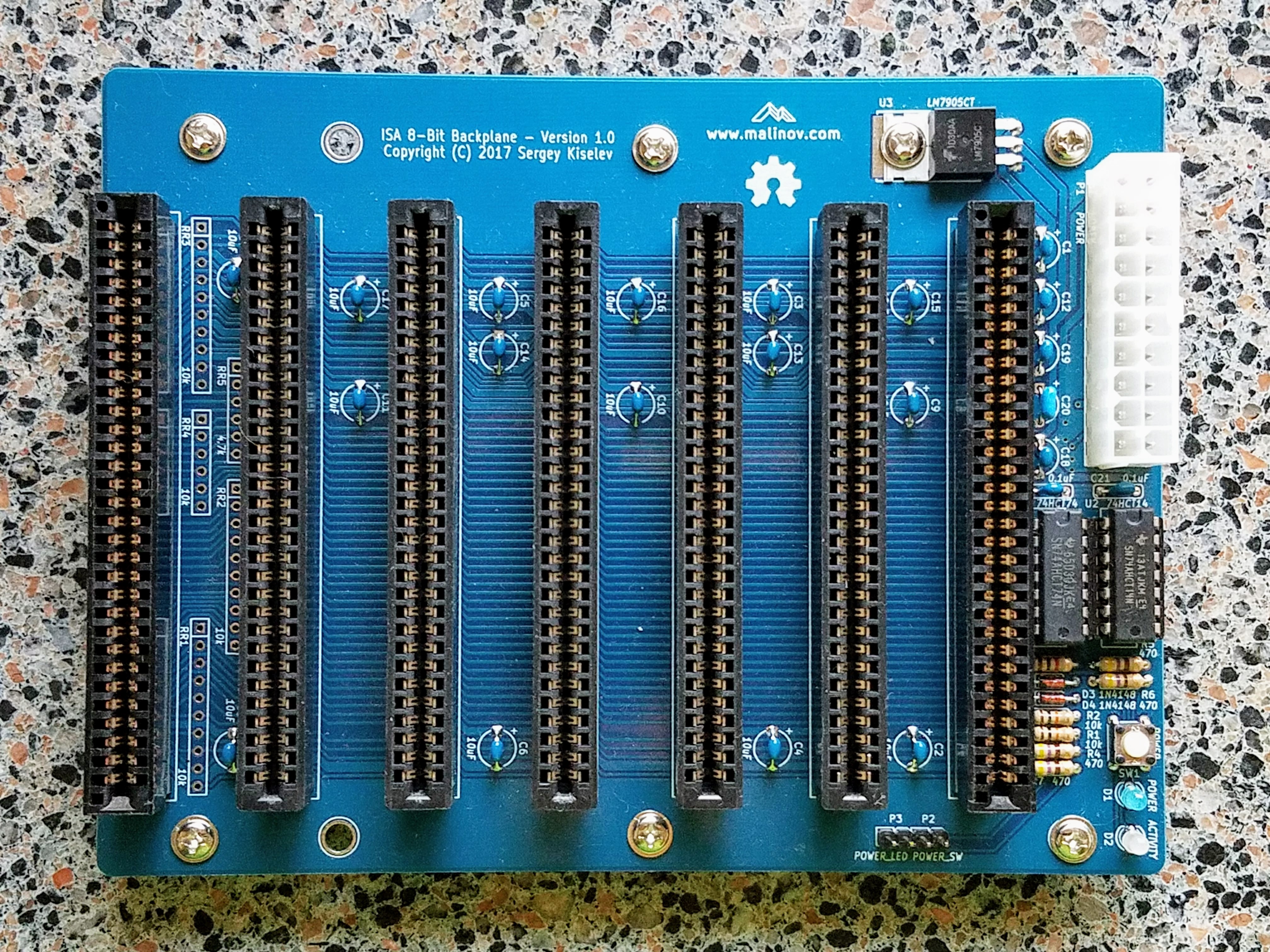
Please refer to Building Instructions page for detailed instructions.
| Pin | Description | Pin | Description |
|---|---|---|---|
| 1 | +3.3V power supply (not used) | 11 | +3.3V power supply (not used) |
| 2 | +3.3V power supply (not used) | 12 | -12V power supply |
| 3 | GND | 13 | Ground |
| 4 | +5V power supply | 14 | Power supply ON signal |
| 5 | Ground | 15 | Ground |
| 6 | +5V power supply | 16 | Ground |
| 7 | Ground | 17 | Ground |
| 8 | Power good (not used) | 18 | -5V power supply (not used)* |
| 9 | +5V standby power supply | 19 | +5V power supply |
| 10 | +12V power supply | 20 | +5V power supply |
Note: -5V is not provided by most ATX power supplies. It is generated using an on board voltage regulator instead
| Pin | Description |
|---|---|
| 1 | Ground |
| 2 | Power ON signal |
| Pin | Description |
|---|---|
| 1 | LED+ |
| 2 | Ground |
Press SW1 to turn power on or off. The SW1 is connected in parallel with P2
ISA 8-bit Backplane project on Mouser.com - View and order all components except of the PCB.
ISA 8-bit Backplane project on OSH Park - View and order the PCB.
| Component type | Reference | Description | Quantity | Possible sources and notes |
|---|---|---|---|---|
| PCB | ISA 8-bit Backplane PCB - Version 1.0 | 1 | Refer to the RetroBrew Computers Board Inventory page for ordering information, or order from a PCB manufacturer of your choice using provided Gerber or KiCad files | |
| Integrated Circuit | U1 | 74HCT74, DIP-14 package | 1 | Mouser 595-SN74AHCT74N |
| Integrated Circuit | U2 | 74HCT14, DIP-14 package | 1 | Mouser 595-SN74AHCT14N |
| Integrated Circuit | U3 | LM7905C -5V voltage regulator | 1 | Mouser 512-LM7905CT |
| IC Socket | U1, U2 | DIP-14, 300 mil socket | 2 | Mouser 517-4814-3000-CP |
| LED | D1 | 3 mm, blue LED indicator | 1 | Mouser 696-SSL-LX3054USBD |
| LED | D2 | 3 mm, bi-color red/green LED indicator | 1 | Mouser 696-SSL-LX3054IGW |
| Diode | D3, D4 | 1N4148 | 2 | Mouser 512-1N4148 |
| Tactile Button | SW1 | 6 mm tactile button, straight | 1 | Mouser 653-B3F-1000 |
| Connector | P1 | 20 pin ATX power connector | 1 | Mouser 538-46015-2006 |
| Connector | P2, P3 | 4 pin header, 2.54 mm pitch | 2 | Mouser 649-68002-104HLF |
| Connector | BUS1-BUS7 | 62 pin card edge connector, 2.54 mm pitch | 7 | Mouser 571-6-5530843-5 |
| Capacitor | C1 - C19 | 10 uF, 16V, MLCC, 5 mm lead spacing | 19 | Mouser 810-FG28X5R1E106MR06 |
| Capacitor | C20 | 1 uF, MLCC, 5 mm lead spacing | 1 | Mouser 810-FG28X5R1H105KRT0 |
| Capacitor | C21, C22 | 0.1 uF, MLCC, 5 mm lead spacing | 2 | Mouser 594-K104K15X7RF53H5 |
| Resistor | R1, R2 | 10 kohm, through hole | 2 | Mouser 291-10K-RC |
| Resistor | R3 | 1 kohm, through hole | 1 | Mouser 291-1K-RC |
| Resistor | R4 - R7 | 470 ohm, through hole | 4 | Mouser 291-470-RC |
| Resistor Array | RR1 - RR5 | do not populate | Optional, should not be populated |
| Qty | Value | Footprint | References |
|---|---|---|---|
| 19 | 10uF | my_components:Cap_Tant_508 | C1, C2, C3, C4, C5, C6, C10, C11, C12, C13, C14, C15, C16, C17, C18, C19 +3 |
| 8 | HOLE | my_components:Hole_4mm | HOLE1, HOLE2, HOLE3, HOLE4, HOLE5, HOLE6, HOLE7, HOLE8 |
| 6 | BUSPC_HOST | my_components:Conn_Edge_ISA8 | BUS2, BUS3, BUS4, BUS5, BUS6, BUS7 |
| 4 | 470 | my_components:Res_762 | R4, R5, R6, R7 |
| 3 | 10k | my_components:Conn_SIL10 | RR1, RR2, RR3 |
| 2 | 0.1uF | my_components:Cap_Cer_508 | C21, C22 |
| 2 | 10k | my_components:Res_762 | R1, R2 |
| 2 | 1N4148 | my_components:Diode_762 | D3, D4 |
| 1 | 10k | my_components:Conn_SIL6 | RR4 |
| 1 | 1k | my_components:Res_762 | R3 |
| 1 | 1uF | my_components:Cap_Tant_508 | C20 |
| 1 | 4.7k | my_components:Conn_SIL6 | RR5 |
| 1 | 74HCT14 | my_components:IC_DIP14_300 | U2 |
| 1 | 74HCT74 | my_components:IC_DIP14_300 | U1 |
| 1 | ACTIVITY | my_components:LED_3mm | D2 |
| 1 | BUSPC_DEV | my_components:Conn_Edge_ISA8 | BUS1 |
| 1 | LM7905CT | my_components:IC_TO220-3_Horiz | U3 |
| 1 | OSHW-logo_silkscreen-front_8mm | OSHW-logo:OSHW-logo_silkscreen-front_8mm | G*** |
| 1 | POWER | my_components:Conn_Power_ATX_20pin | P1 |
| 1 | POWER | my_components:LED_3mm | D1 |
| 1 | POWER | my_components:Switch_Tactile_6mm | SW1 |
| 1 | POWER_LED | my_components:Conn_Pin_Header_2x1_2.54mm | P3 |
| 1 | POWER_SW | my_components:Conn_Pin_Header_2x1_2.54mm | P2 |
It measures 116.8 × 154.9 mm and has 2 copper layers, 1.6 mm thick.
61 parts, built around the 74HCT14D, 74HCT74D and LM7905CT. The full list of its parts is on this page, with links to each part's symbol and footprint where PCBKit's library has them.
From the skiselev/isa8_backplane repository on GitHub, at the commit this page was made from: the board is KiCad/isa_backplane.kicad_pcb. PCBKit opens the board in the browser, with nothing to install.
Its repository publishes it under the GPL-3.0 licence: you may reuse it on that licence's terms (keep the author's notice, and for a copyleft licence share your changes alike).


schlae/snark-barker-mca
A Sound Blaster compatible sound card for Micro Channel bus computers


FredericSegard/Fr80
Z80 Homebrew computer, code-named Fre80, pronounced Freddy.