
2 layers33 × 58.8 mm

 simonceglarz/self-balancing-rc-robot1
ESP32 Self Balancing Remote Controleld Pendulum Bot.
Balancing robot pcb is an open-source printed circuit board by simonceglarz, from the simonceglarz/self-balancing-rc-robot repository on GitHub. It is a 2-layer board of 120 × 70 mm with 48 parts on 51 nets, routed with 473 tracks and 104 vias.
It is built around the LSM6DSOX. Its parts include 17 connectors, 8 capacitors, 8 resistors, 1 diode and 1 switch. It belongs with the robots and motor control boards and the ESP32 boards of this library.
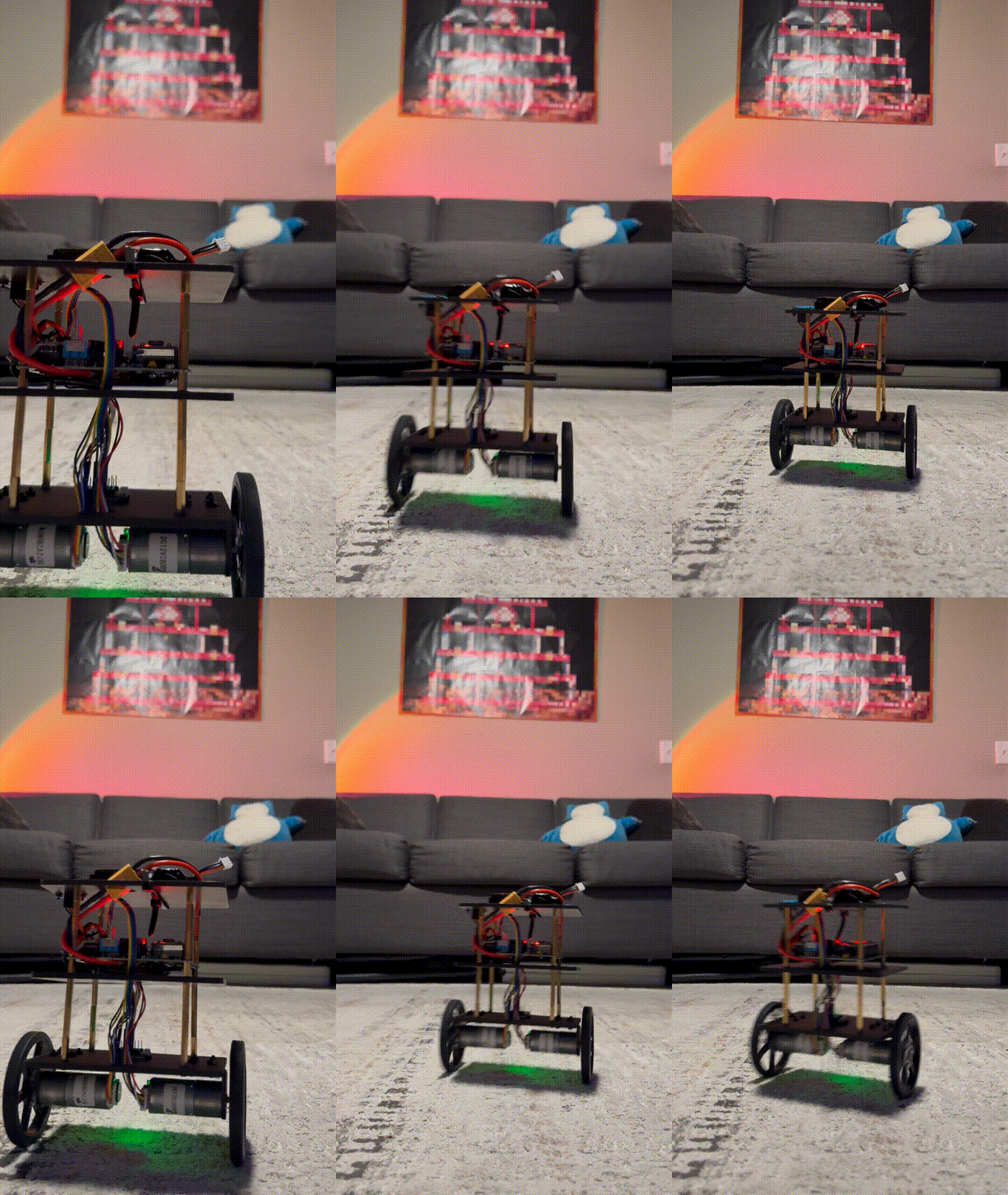
A two-wheeled self-balancing robot built around an ESP32, an IMU, and a cascaded PID control loop — with a live WiFi tuning interface and a dedicated wireless joystick controller.
This robot balances on two wheels using a complementary filter for orientation estimation and a two-loop (cascaded) PID controller: an inner loop holds the body upright, and an outer loop corrects for long-term drift by tracking wheel velocity from quadrature encoders. It can be driven and steered two ways — a phone/browser joystick served directly from the robot's own WiFi access point, or a dedicated physical ESP32 + analog-joystick controller communicating over ESP-NOW.
| Component | Notes |
|---|---|
| ESP32 dev board (x2) | one for the robot, one for the joystick controller |
| Adafruit LSM6DSOX | 6-axis IMU (accelerometer + gyro) |
| SSD1306 OLED (128x64, I2C) | onboard telemetry display |
| 2x DC motor + quadrature encoders | drive + odometry |
| Motor driver (dual H-bridge) | AIN1/AIN2, BIN1/BIN2 control |
| 2-axis analog joystick module | physical controller input |
| LiPo battery + voltage divider | robot power + monitoring via analogReadMilliVolts() |
| Buck regulator (Adafruit MPM3610, 5V) | steps the 7.4V 2S LiPo down to 5V for the ESP32 |
| Reverse-polarity protection (1N5822 Schottky) | sits ahead of the buck input, ~0.35V drop |
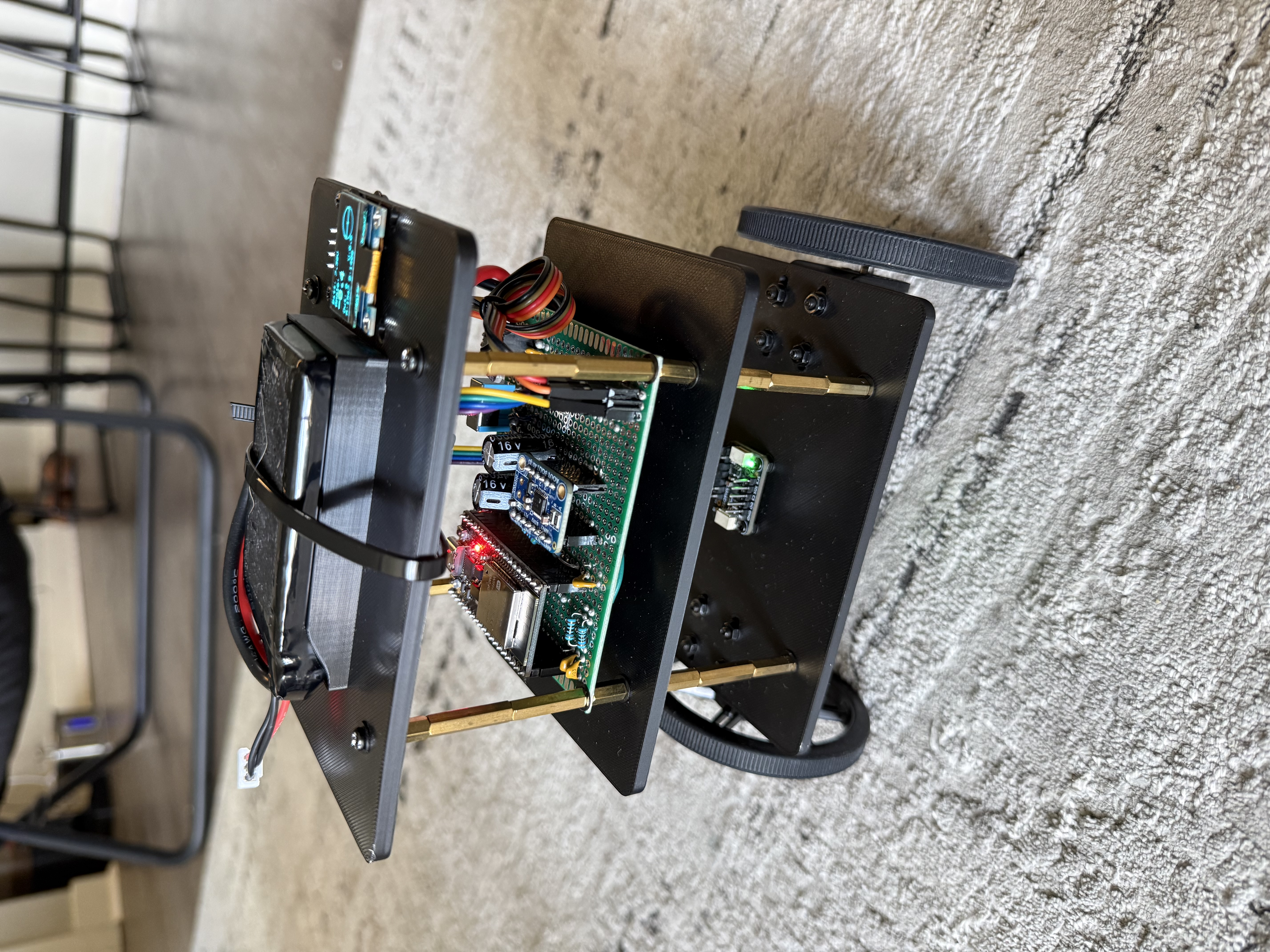 | 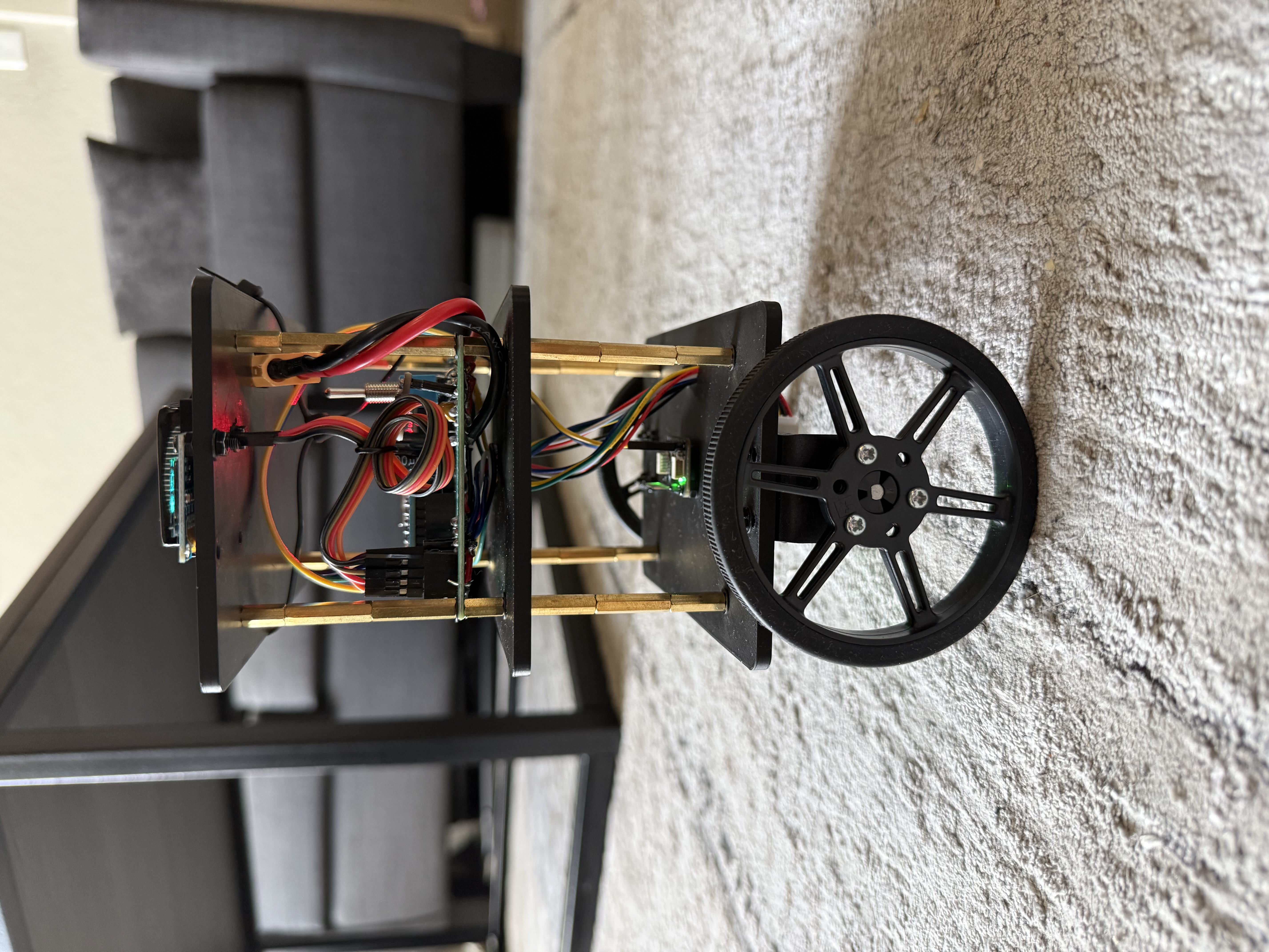 |
| Assembled 3-layer 3D-printed chassis — top plate carries the LiPo battery and OLED, middle plate holds the ESP32, IMU, and perfboard wiring, bottom plate mounts the motor driver. Brass standoffs separate the layers. | Rear view showing inter-layer wiring and one of the two drive wheels. |
IMU (accel + gyro) ──► complementary filter ──► angle estimate
                                                     │
                          ┌──────────────────────────┘
                          ▼
              inner loop: PID(Kp, Ki, Kd) on angle error
                          │
              outer loop: velocity/drift correction
              (encoder-derived velocity → Kp_vel/Ki_vel → shifts
               the angle setpoint to correct long-term drift)
                          │
                          ▼
        per-motor floor rescale + hysteresis deadband
                          │
                          ▼
                   motorA() / motorB() (PWM)
Input arrives from either the WebSocket ('J:x:y' from the webpage joystick, or discrete gain/calibration updates from the tuning sliders) or ESP-NOW (the physical joystick controller) — both write into the same targetAngleTrim/steerBias variables, so the control loop doesn't care which source is driving it.
2S LiPo (7.4V nominal, 8.4V full) │ ▼ 1N5822 Schottky diode (reverse-polarity protection, ~0.35V drop) │ ▼ power node ──┬── DRV8833 VM (motors run off the unregulated battery rail) ├── 2× 1000µF bulk caps + 100nF ceramic → GND └── MPM3610 buck regulator (Vin) │ ▼ 5V out → ESP32 5V pin │ ▼ ESP32 internal LDO → 3.3V rail │ ┌───────────┼───────────┐ ▼ ▼ ▼ IMU + OLED Encoder VCC DRV8833 SLP (I2C) (must be held high or driver sleeps)
Motors draw directly off the unregulated battery rail (through the protection diode) since they don't need clean power; logic and sensors run off the regulated 5V → 3.3V chain, which does.
Bench-verified (multimeter):
| Measurement point | Reading |
|---|---|
| Diode cathode (post-protection) | 8.05 V |
| MPM3610 output | 5.00 V |
| ESP32 3.3V pin | 3.32 V |
| Battery rail under full motor load | 7.77 V (no sag — bulk caps holding) |
The perfboard is being replaced by a 2-layer KiCad PCB (120 \C3\97 70 mm) that carries the ESP32, motor driver and buck converter on sockets.
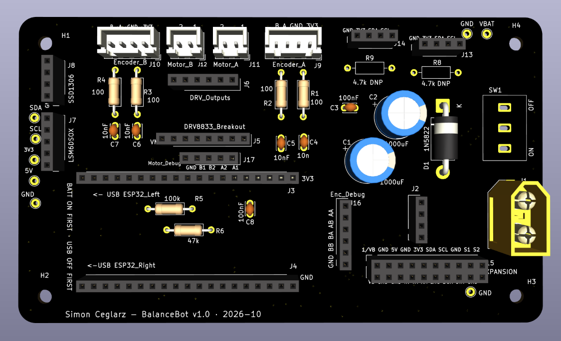
#define PCB_REV1Status: ordered from JLCPCB, bring-up in progress. Full write-up, pinouts and design notes: pcb/README.md
Each firmware is its own PlatformIO project.
Robot (robot/):
pio run --target upload from within robot/BalanceBot AP and open http://<AP IP>/ for the tuning pageController (controller/):
robotMac[] in controller/src/main.cpp to the robot's printed AP MAC addressWIFI_CHANNEL matches between both projectspio run --target upload from within controller/Both projects are pinned to the same platform version (see each platformio.ini) — this matters, since ESP-NOW callback signatures changed between core versions and mismatched cores between the two boards can cause hard-to-diagnose link failures.
[MIN_OUTPUT, MAX_OUTPUT] per motor instead of snapping.avgVelocity should combine the two encoders by addition or subtraction meant understanding what each raw sign actually meant physically (translation vs. yaw), not just trying both and picking whichever "looked less bad." Verified empirically with a manual push test (motors disabled, print raw deltas) rather than guessing.ANGLE_TRIM_DEG (the sensor-to-mechanical zero offset) drifts somewhat run-to-run; auto-calibration was considered but not implemented.| Qty | Value | Footprint | References |
|---|---|---|---|
| 4 | 100 | Resistor_THT:R_Axial_DIN0207_L6.3mm_D2.5mm_P10.16mm_Horizontal | R1, R2, R3, R4 |
| 4 | MountingHole | MountingHole:MountingHole_3.2mm_M3 | H1, H2, H3, H4 |
| 3 | 10nF | Capacitor_THT:C_Disc_D3.0mm_W2.0mm_P2.50mm | C5, C6, C7 |
| 3 | GND | TestPoint:TestPoint_THTPad_D2.0mm_Drill1.0mm | TP6, TP7, TP8 |
| 2 | 1000uF | Capacitor_THT:CP_Radial_D10.0mm_P5.00mm | C1, C2 |
| 2 | 100nF | Capacitor_THT:C_Disc_D3.0mm_W2.0mm_P2.50mm | C3, C8 |
| 2 | 4.7k | Resistor_THT:R_Axial_DIN0207_L6.3mm_D2.5mm_P10.16mm_Horizontal | R8, R9 |
| 1 | 100k | Resistor_THT:R_Axial_DIN0207_L6.3mm_D2.5mm_P10.16mm_Horizontal | R5 |
| 1 | 10n | Capacitor_THT:C_Disc_D3.0mm_W2.0mm_P2.50mm | C4 |
| 1 | 1N5822 | Diode_THT:D_DO-201AD_P15.24mm_Horizontal | D1 |
| 1 | 3V3 | TestPoint:TestPoint_THTPad_D2.0mm_Drill1.0mm | TP3 |
| 1 | 47k | Resistor_THT:R_Axial_DIN0207_L6.3mm_D2.5mm_P10.16mm_Horizontal | R6 |
| 1 | 5V | TestPoint:TestPoint_THTPad_D2.0mm_Drill1.0mm | TP2 |
| 1 | <- USB ESP32_Left | Connector_PinSocket_2.54mm:PinSocket_1x19_P2.54mm_Vertical | J3 |
| 1 | <-USB ESP32_Right | Connector_PinSocket_2.54mm:PinSocket_1x19_P2.54mm_Vertical | J4 |
| 1 | DRV8833_Breakout | Connector_PinSocket_2.54mm:PinSocket_1x08_P2.54mm_Vertical | J5 |
| 1 | DRV_Outputs | Connector_PinSocket_2.54mm:PinSocket_1x06_P2.54mm_Vertical | J6 |
| 1 | EXPANSION | Connector_PinSocket_2.54mm:PinSocket_2x10_P2.54mm_Vertical | J15 |
| 1 | Enc_Debug | Connector_PinSocket_2.54mm:PinSocket_1x06_P2.54mm_Vertical | J16 |
| 1 | Encoder_A | Connector_JST:JST_XH_B4B-XH-A_1x04_P2.50mm_Vertical | J9 |
| 1 | Encoder_B | Connector_JST:JST_XH_B4B-XH-A_1x04_P2.50mm_Vertical | J10 |
| 1 | I2C_B_1 | Connector_PinSocket_2.54mm:PinSocket_1x04_P2.54mm_Vertical | J13 |
| 1 | I2C_B_2 | Connector_PinSocket_2.54mm:PinSocket_1x04_P2.54mm_Vertical | J14 |
| 1 | LSM6DSOX | Connector_PinSocket_2.54mm:PinSocket_1x05_P2.54mm_Vertical | J7 |
| 1 | MPM3610_Breakout | Connector_PinSocket_2.54mm:PinSocket_1x04_P2.54mm_Vertical | J2 |
| 1 | Motor_A | Connector_JST:JST_XH_B2B-XH-A_1x02_P2.50mm_Vertical | J11 |
| 1 | Motor_B | Connector_JST:JST_XH_B2B-XH-A_1x02_P2.50mm_Vertical | J12 |
| 1 | Motor_Debug | Connector_PinSocket_2.54mm:PinSocket_1x05_P2.54mm_Vertical | J17 |
| 1 | PWR_SW | balancing_robot_pcb:SW_MTS102_SPDT_3Pin | SW1 |
| 1 | QR_LinkedIn_14.8mm | QR_Logos:QR_LinkedIn_14.8mm | LOGO** |
| 1 | SCL | TestPoint:TestPoint_THTPad_D2.0mm_Drill1.0mm | TP5 |
| 1 | SDA | TestPoint:TestPoint_THTPad_D2.0mm_Drill1.0mm | TP4 |
| 1 | SSD1306 | Connector_PinSocket_2.54mm:PinSocket_1x04_P2.54mm_Vertical | J8 |
| 1 | VBAT | TestPoint:TestPoint_THTPad_D2.0mm_Drill1.0mm | TP1 |
| 1 | XT60_Battery | Connector_AMASS:AMASS_XT60-M_1x02_P7.20mm_Vertical | J1 |


dhruv1859/CARVantaBAC
🧬 CARVanta Next-Generation Precision Oncology & AI CAR-T Cell Platform Interactive 3D Biological Digital Twin • 3D Neural Bridge • Sentinel HYDRA Biosensor

khawlahhouki/fatigue-detection-edge-ai
Real-time physical fatigue detection using Edge AI on STM32H7 with FreeRTOS, biosignal acquisition (PPG, EMG, IMU) and TFLite INT8 inference


AidenBTTU/Gesture-Capture-Watch
A wristband-mounted gesture recognition system built around an STM32F411, IMU, and OLED display, with USB-C battery charging and ESD-protected I/O.

It measures 120 × 70 mm and has 2 copper layers, 1.6 mm thick.
48 parts, built around the LSM6DSOX. The full list of its parts is on this page, with links to each part's symbol and footprint where PCBKit's library has them.
From the simonceglarz/self-balancing-rc-robot repository on GitHub, at the commit this page was made from: the board is pcb/kicad/balancing_robot_pcb.kicad_pcb and its schematic pcb/kicad/balancing_robot_pcb.kicad_sch. PCBKit opens the board in the browser, with nothing to install.
Its repository states no licence, so its author keeps all rights: ask simonceglarz before reusing the design.