
4 layers98 × 130 mm
Upper 6 bits - Module ID - max 0x3F Lower 5 bits - Command ID - max 0x1F CAN ID = (Module ID Default Module ID : 0x200 (Standard)
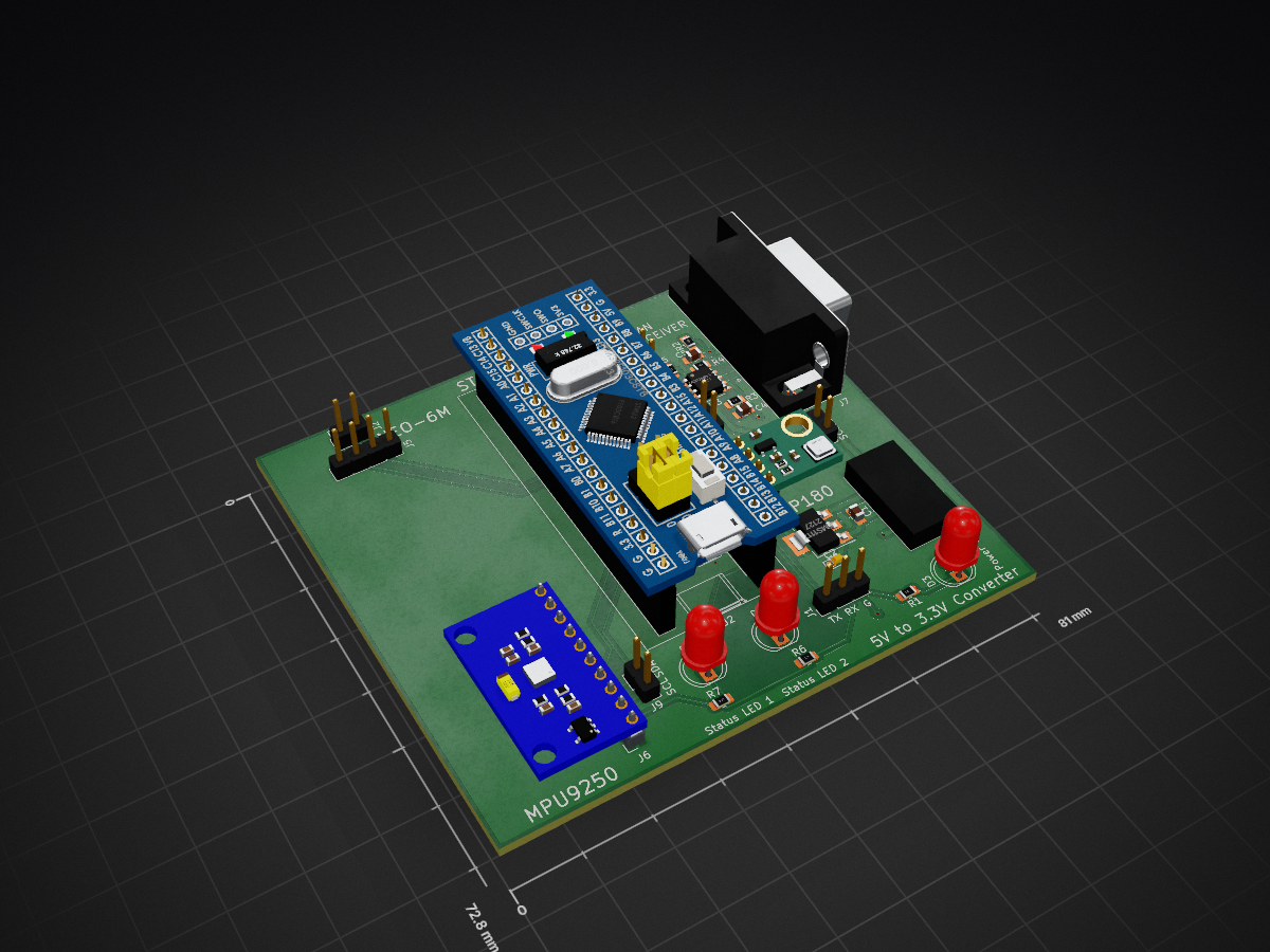
GPS INS PCB is an open-source printed circuit board by siddarthiyer, from the siddarthiyer/GPS-aided-Inertial-Navigation-System-Module repository on GitHub. It is a 2-layer board of 81 × 72.8 mm with 29 parts on 61 nets, routed with 145 tracks and 8 vias.
It is built around the STM32F103C8T6, MCP2551-I/SN-HG and NEO-6M, with the BMP180 and AMS1117 among its other parts. Its parts include 9 connectors, 7 resistors, 5 capacitors, 3 ICs and 3 diodes. It belongs with the radio and wireless and interfaces and adapters boards and the STM32 boards of this library.


Upper 6 bits - Module ID - max 0x3F
Lower 5 bits - Command ID - max 0x1F
CAN ID = (Module ID << 5) | Command ID
Default Module ID : 0x200 (Standard)
| CMD_ID | Name | Sender | Signals | Start byte | Signal Type | Bits |
|---|---|---|---|---|---|---|
0x001 | Heartbeat | Module | Latitude, Longitude | 0, 4 | IEEE 754 Float, IEEE 754 Float | 32, 32 |
MPU-9250
NEO-6M
BMP180

| Qty | Value | Footprint | References |
|---|---|---|---|
| 3 | 220R | Resistor_SMD:R_0805_2012Metric_Pad1.20x1.40mm_HandSolder | R1, R6, R7 |
| 2 | 100R | Resistor_SMD:R_0805_2012Metric_Pad1.20x1.40mm_HandSolder | R3, R4 |
| 2 | 560pf | Capacitor_SMD:C_0805_2012Metric_Pad1.18x1.45mm_HandSolder | C4, C5 |
| 1 | 0.1 uf | Capacitor_SMD:C_0805_2012Metric_Pad1.18x1.45mm_HandSolder | C3 |
| 1 | 10uf | Capacitor_SMD:C_0805_2012Metric_Pad1.18x1.45mm_HandSolder | C1 |
| 1 | 120R | Resistor_SMD:R_0805_2012Metric_Pad1.20x1.40mm_HandSolder | R5 |
| 1 | 120R Jumper | Connector_PinHeader_2.54mm:PinHeader_1x02_P2.54mm_Vertical | 120R JP |
| 1 | 22uf | Capacitor_Tantalum_SMD:CP_EIA-1608-08_AVX-J_Pad1.25x1.05mm_HandSolder | C2 |
| 1 | 4k7 | Resistor_SMD:R_0805_2012Metric_Pad1.20x1.40mm_HandSolder | R2 |
| 1 | AMS1117 | Package_TO_SOT_SMD:SOT-223-3_TabPin2 | U1 |
| 1 | BMP180 | Connector_PinSocket_2.54mm:PinSocket_1x04_P2.54mm_Vertical | J4 |
| 1 | BMP180_Debug | Connector_PinHeader_2.54mm:PinHeader_1x02_P2.54mm_Vertical | J3 |
| 1 | CAN_Debug | Connector_PinHeader_2.54mm:PinHeader_1x02_P2.54mm_Vertical | J8 |
| 1 | DB9_CAN_CONN | Connector_Dsub:DSUB-9_Male_Horizontal_P2.77x2.84mm_EdgePinOffset4.94mm_Housed_MountingHolesOffset7.48mm | J7 |
| 1 | IMU_Debug | Connector_PinHeader_2.54mm:PinHeader_1x02_P2.54mm_Vertical | J9 |
| 1 | MCP2551-I-SN | Package_SO:SOIC-8_3.9x4.9mm_P1.27mm | U3 |
| 1 | MPU9250 | Connector_PinSocket_2.54mm:PinSocket_1x10_P2.54mm_Vertical | J6 |
| 1 | NEO-6M | Connector_PinSocket_2.54mm:PinSocket_1x04_P2.54mm_Vertical | J5 |
| 1 | NEO-6M_Debug | Connector_PinHeader_2.54mm:PinHeader_1x02_P2.54mm_Vertical | J2 |
| 1 | Power_LED | LED_THT:LED_D5.0mm | D3 |
| 1 | STM32F103C8T6 | Footprints:YAAJ_BluePill_1 | U2 |
| 1 | Status_LED_Blue | LED_THT:LED_D5.0mm | D1 |
| 1 | Status_LED_Red | LED_THT:LED_D5.0mm | D2 |
| 1 | UART | Connector_PinHeader_2.54mm:PinHeader_1x03_P2.54mm_Vertical | J1 |
| 1 | XT60_YELLOW | XT60_YELLOW:AMASS_XT60PB-M | Q1 |

heimdilon/stm32f103c8t6-devboard
Custom STM32F103C8T6 development board designed in KiCad and hand-assembled as a prototype.

LKbrilliant/Brilliant-Reflow
A complete DIY solution for converting a consumer oven into a temperature controlled reflow oven for PCB soldering

shrivastavprangya/STM32-MICROCONTROLLER-USB-DEVELOPMENT-BOARD
Custom STM32 microcontroller USB development board designed using KiCad. Includes LDO based 3.3V power regulation, external crystal oscillator, decoupling capacitors, USB interface and GPIO expansion headers on a…


Ahaz387/STM-32
This project is a custom PCB designed around an STM32 microcontroller for embedded systems development and peripheral interfacing.

hughmancoder/stm32-PCB-design
PCB Design for STM32F103C8T6 Microcontroller built with KiCAD

It measures 81 × 72.8 mm and has 2 copper layers, 1.6 mm thick.
29 parts, built around the STM32F103C8T6, MCP2551-I/SN-HG, NEO-6M and BMP180. The full list of its parts is on this page, with links to each part's symbol and footprint where PCBKit's library has them.
From the siddarthiyer/GPS-aided-Inertial-Navigation-System-Module repository on GitHub, at the commit this page was made from: the board is Hardware/GPS_INS_PCB/GPS_INS_PCB.kicad_pcb and its schematic Hardware/GPS_INS_PCB/GPS_INS_PCB.kicad_sch. PCBKit opens the board in the browser, with nothing to install.
Its repository states no licence, so its author keeps all rights: ask siddarthiyer before reusing the design.