2 layers100 × 100 mm
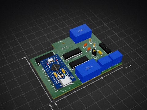
Flipdot H Bridge
comakingspace/FlipDotDisplay
They were bought at the Makerfaire Hannover 2016.
76 parts3

 Shreya676/motor_driver
motor driver schematic and pcb design
Motordr is an open-source printed circuit board by Shreya676, from the Shreya676/motor_driver repository on GitHub. It is a 2-layer board of 44 × 36 mm with 9 parts on 12 nets, routed with 73 tracks and 0 vias.
It is built around the L293D and L7805. Its parts include 4 connectors, 2 ICs, 1 resistor and 1 diode. It belongs with the robots and motor control boards of this library.


This circuit utilizes the L293D to control the direction of two DC motors based on digital input signals. It also includes a 5V regulator for powering the control logic and a power indicator LED.
U1: L293D - Quadruple Half-H Driver: An integrated circuit containing four half-H bridge drivers, enabling bidirectional control of DC motors.
U3: L7805 - 5V Voltage Regulator: A linear regulator that provides a stable 5V output for the logic circuitry.
J1: Conn_01x04_Pin - Control Input Connector: A 4-pin connector for applying digital control signals to the L293D.
J2: Screw_Terminal_01x02 - Motor Power Input: A 2-pin screw terminal for connecting the higher voltage power supply for the motors and the input of the L7805.
J3: Screw_Terminal_01x02 - Motor Output 1: A 2-pin screw terminal for connecting the first motor.
J4: Screw_Terminal_01x02 - Motor Output 2: A 2-pin screw terminal for connecting the second motor.
D1: LED - Power Indicator: An LED that illuminates when the 5V power supply is active.
R1: 1kΩ Resistor: A current-limiting resistor for the power indicator LED.
PWR_FLAG: Net label for the regulated 5V power supply rail.
GND: Net label for the common ground connection.
Logic Power: A higher DC voltage is supplied to J2. The L7805 (U3) regulates this voltage to 5V (PWR_FLAG), powering the control logic of the L293D (VCC1). The LED (D1) indicates the presence of this 5V.
Motor Power: The higher DC voltage from J2 also powers the motor driving stage of the L293D (VCC2).
Control Inputs: Digital signals applied to J1 are fed into the input pins (1A, 2A, 3A, 4A) and enable pins (EN1,2, EN3,4) of the L293D.
Enabling Motors: To drive a motor connected to J3 or J4, the corresponding enable pin(s) on the L293D must be high.
Direction Control: The logic levels on the input pins (e.g., 1A and 2A for the motor at J3) determine the direction of current flow through the motor, thus controlling its rotation direction. The L293D internally switches the power to the motor based on these inputs.
Motor Output: The L293D outputs the controlled power to the motors connected at J3 and J4, allowing for bidirectional control of two independent DC motors.
| Qty | Value | Footprint | References |
|---|---|---|---|
| 2 | MOTOR1 | TerminalBlock_Phoenix:TerminalBlock_Phoenix_MKDS-1,5-2-5.08_1x02_P5.08mm_Horizontal | J2, J3 |
| 1 | 1k | Resistor_THT:R_Axial_DIN0204_L3.6mm_D1.6mm_P5.08mm_Horizontal | R1 |
| 1 | Conn_01x04_Pin | Connector:FanPinHeader_1x04_P2.54mm_Vertical | J1 |
| 1 | L293D | Package_DIP:DIP-16_W7.62mm | U1 |
| 1 | L7805 | Package_TO_SOT_THT:TO-220-3_Vertical | U3 |
| 1 | LED | LED_THT:LED_D3.0mm | D1 |
| 1 | LOGO | LOGO | G*** |
| 1 | Screw_Terminal | TerminalBlock_Phoenix:TerminalBlock_Phoenix_MKDS-1,5-2-5.08_1x02_P5.08mm_Horizontal | J4 |
comakingspace/FlipDotDisplay
They were bought at the Makerfaire Hannover 2016.


Yourself1011/sumo-bot
The code for Li Feng Yin and Daniel Zhang's sumo robot, for TEJ3MI


mrpossoms/openturret
Opensource designs and software for autonomously aiming gimble

It measures 44 × 36 mm and has 2 copper layers, 1.6 mm thick.
9 parts, built around the L293D and L7805. The full list of its parts is on this page, with links to each part's symbol and footprint where PCBKit's library has them.
From the Shreya676/motor_driver repository on GitHub, at the commit this page was made from: the board is motordr.kicad_pcb and its schematic motordr.kicad_sch. PCBKit opens the board in the browser, with nothing to install.
Its repository states no licence, so its author keeps all rights: ask Shreya676 before reusing the design.