Skip to the content
PCBKitNew board
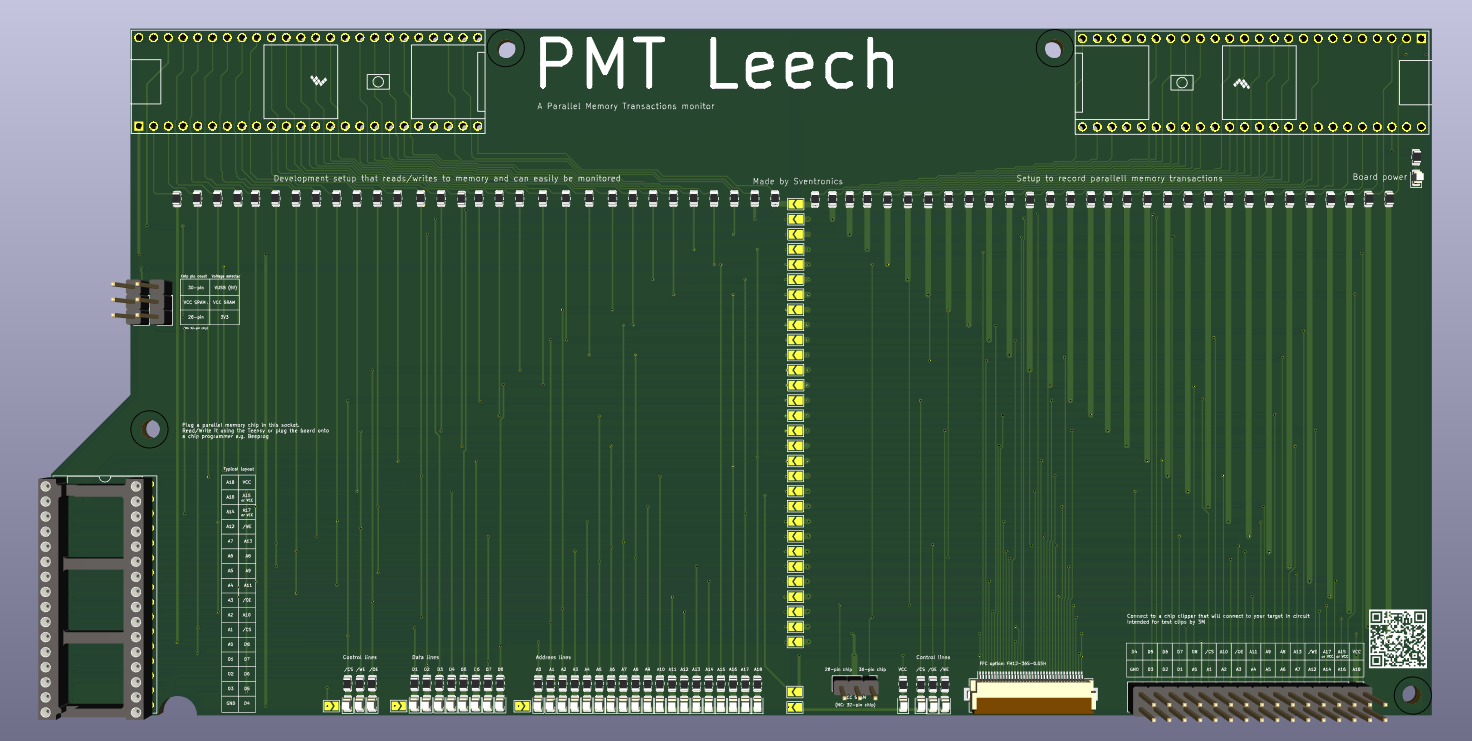
2 layers238 × 118.4 mmRAMON DEV, the printed circuit board in 3D

PMT Leech is especially useful when working with older electronic systems that meet these two conditions: - ✅ The system uses a parallel memory chip (like SRAM or EPROM) - ✅ The CPU operates with an external clock input

Size
238 × 118.4 mm
Copper layers
2
Thickness
1.6 mm
Parts
183
Nets
197
Pads
549
Tracks, vias
1,913, 283
Pours
2
Routed
Yes
KiCad
KiCad 8.0 (file 20240108)
Created
24 Feb 2025
Updated
16 Oct 2025

Overview

RAMON DEV is an open-source printed circuit board by Sfeeen, from the Sfeeen/PMTleech repository on GitHub. It is a 2-layer board of 238 × 118.4 mm with 183 parts on 197 nets, routed with 1,913 tracks and 283 vias.

It is built around the TEENSY 4.1. Its parts include 95 resistors, 35 diodes, 6 connectors and 2 ICs. It belongs with the NXP (LPC, Kinetis, i.MX RT) boards of this library.

Main components

1

README

README.md

🚀 PMT Leech

A Parallel Memory Transactions Monitor
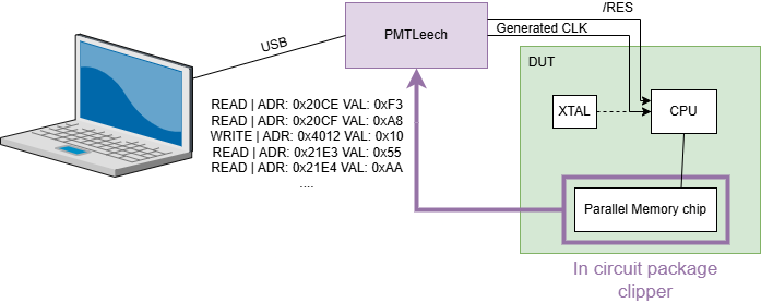
PMT Leech Concept

PMT Leech is a hardware + software tool that lets you monitor live memory accesses from a CPU to an external parallel memory chip.
It streams transactions in real-time, while giving you full control over the system clock — allowing pausing, stepping, and instruction-level debugging.


🔧 When Should You Use PMT Leech?

PMT Leech is especially useful when working with older electronic systems that meet these two conditions:

  • ✅ The system uses a parallel memory chip (like SRAM or EPROM)
  • ✅ The CPU operates with an external clock input

⚙️ How It Works

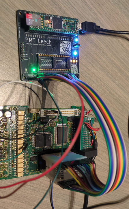
By attaching PMT Leech to your memory chip (via clipper) and supplying your own clock signal to the CPU:

  • You gain live streaming of memory transactions
  • You can pause or step through firmware execution
  • You can reverse engineer or debug embedded firmware in a safe, controlled way

🧰 Hardware Overview
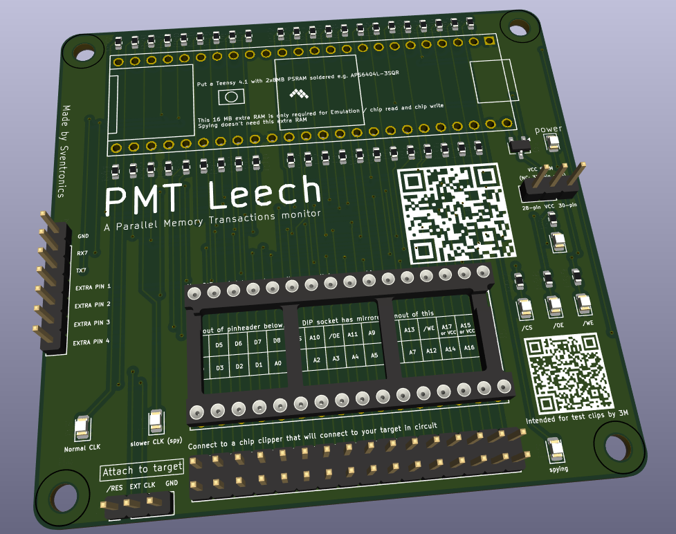
PMT Leech PCB PMT Leech In Use


🖥️ Software Features

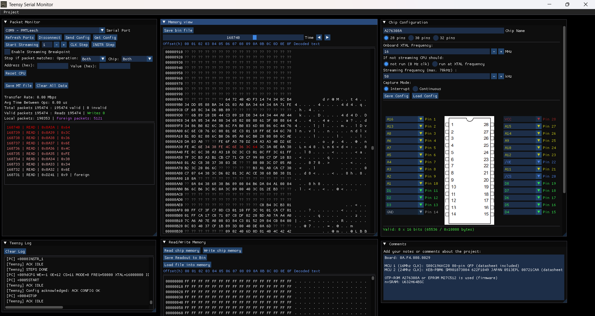
PMT Leech Software

  • 🧩 Configurable pinout: Supports 28, 30, or 32-pin chips
  • 📡 Live recording of transactions (up to 70kHz)
  • 🎨 Interactive memory viewer with color-coded highlights
  • ⏱ Step by clock or instruction
  • 🧠 Detect and label foreign packets (from other devices on the memory bus)
  • 💾 Off-circuit memory read/write with chip socket

🎞️ Demo
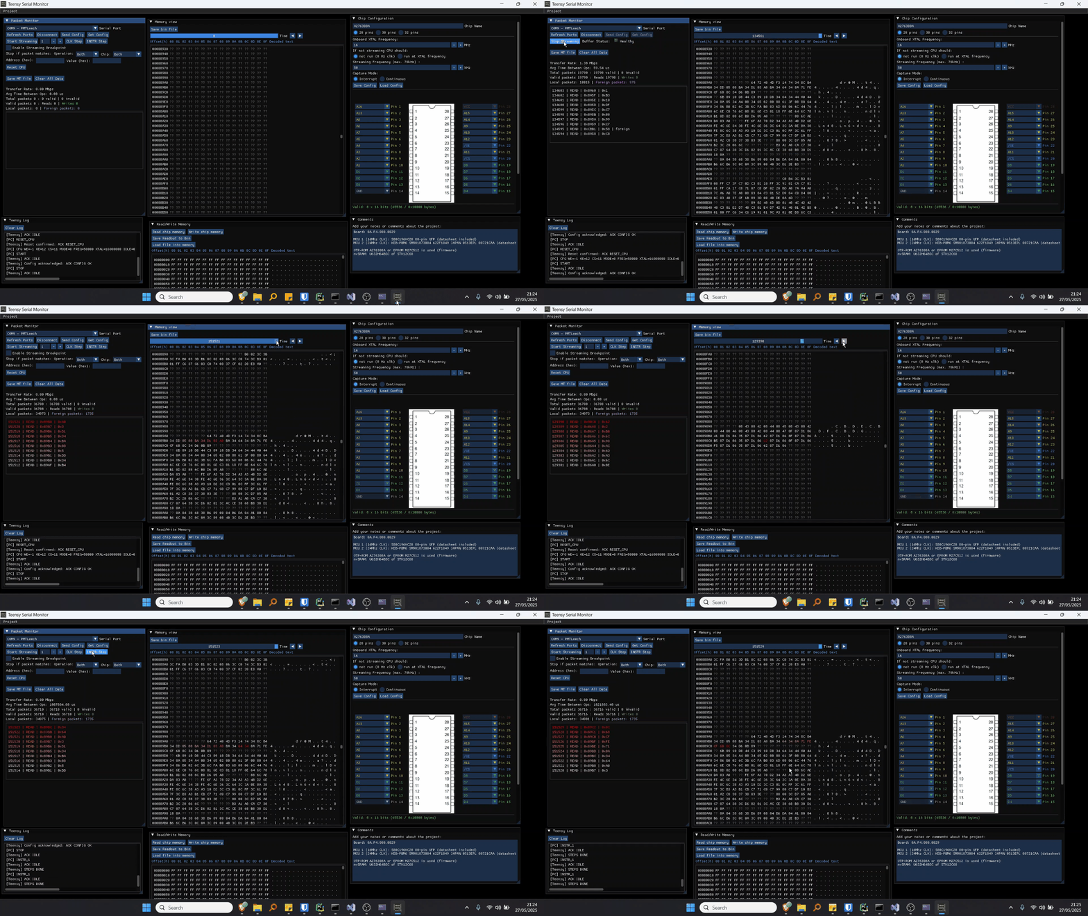
Demo Animation


📋 Requirements

✅ Memory Chip

  • Parallel bus
  • ≤ 8-bit data
  • ≤ 18 address lines
  • 5V compatible (or use 330Ω series resistors)

✅ CPU

  • Must allow external clock input
  • 5V compatible (or 330Ω resistors)

⚠️ Note on Timing

The CPU will be underclocked (e.g., 8 MHz → 50 kHz). This may affect peripherals like UART:

  • Ex: 9600 baud becomes ~60 baud — comms may break.

🧲 In-Circuit Clip Options

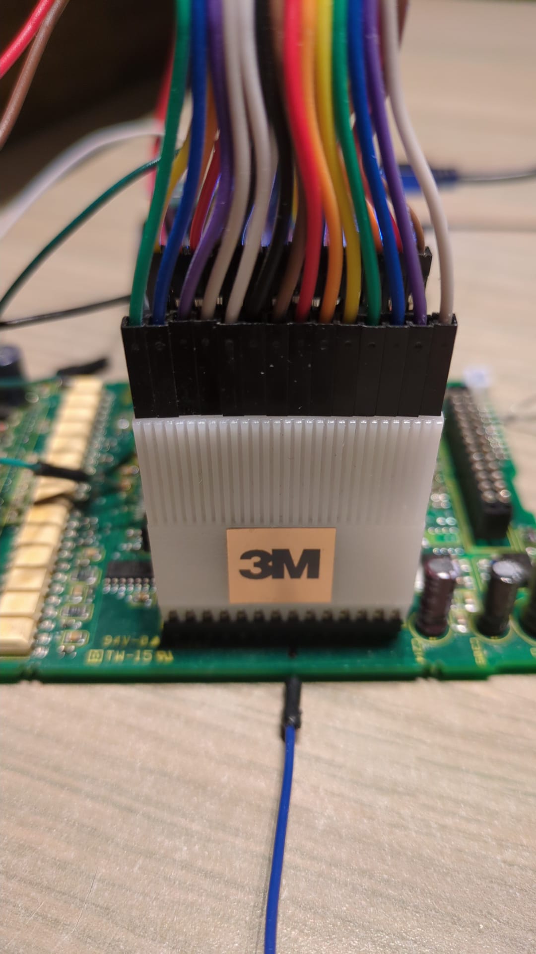
3M Clips Clipper Photo


🧠 Supported Memory Types

  • EEPROM
  • EPROM
  • SRAM — especially valuable for volatile firmware systems

💡 Many older systems used SRAM for firmware due to speed advantages. PMT Leech lets you read these volatile setups without desoldering.


🔍 Example Use Cases

  • Bypass password protection: Record firmware transactions during password validation and discover comparison logic or values.
  • Firmware reverse engineering: Step through opcode streams and infer instruction flow.
  • Brownout glitching: Control timing to inject faults and analyze behavior.

🛠️ Hardware Revisions

PMT Leech v2 (Current)

PMT Leech v2

PMT Leech v1 (Development Stage)

PMT Leech v1


📧 Contact: svenonderbeke [at] hotmail [dot] com
More info to be added soon.


☕ Support

If you’d like to support the development of PMT Leech, you can donate via Ko-fi: Buy Me a Coffee

🧪 Version

Current Version: PMT Leech v2

Parts

183
QtyValueFootprintReferences
95330RResistor_SMD:R_0805_2012MetricR1, R2, R10, R11, R12, R13, R14, R15, R16, R17, R18, R19, R20, R21, R22, R23 +79
39SolderJumper_2_OpenJumper:SolderJumper-2_P1.3mm_Open_TrianglePad1.0x1.5mmJP1, JP2, JP10, JP11, JP12, JP13, JP14, JP15, JP16, JP17, JP18, JP19, JP20, JP21, JP22, JP23 +23
35LEDLED_SMD:LED_0805_2012MetricD1, D2, D10, D11, D12, D13, D14, D15, D16, D17, D18, D19, D20, D21, D22, D23 +19
4MountingHoleMountingHole:MountingHole_3.2mm_M3H1, H2, H3, H4
3Conn_01x03Connector_PinHeader_2.54mm:PinHeader_1x03_P2.54mm_VerticalJ2, J6, J7
2Teensy4.1teensy.pretty-master:Teensy41U1, U13
1Conn_02x16_Counter_Clockwiseclockwise_connectors:PinHeader_2x16_P2.54mm_Vertical_clockwiseJ8
1Conn_02x16_Counter_ClockwisePackage_DIP:DIP-32_W15.24mm_SocketJ1
1Conn_02x18_Counter_ClockwiseConnector_FFC-FPC:Hirose_FH12-36S-0.5SH_1x36-1MP_P0.50mm_HorizontalJ4
1LOGOimages:clippers_QR_2G***
1LOGOimages:github_QR2G***

Questions

How big is the RAMON DEV PCB?

It measures 238 × 118.4 mm and has 2 copper layers, 1.6 mm thick.

What parts does the RAMON DEV use?

183 parts, built around the TEENSY 4.1. The full list of its parts is on this page, with links to each part's symbol and footprint where PCBKit's library has them.

Where can I download the RAMON DEV KiCad files?

From the Sfeeen/PMTleech repository on GitHub, at the commit this page was made from: the board is hardware_development/RAMON_DEV/RAMON_DEV.kicad_pcb and its schematic hardware_development/PMTLeechv2/PMTLeechv2.kicad_sch. PCBKit opens the board in the browser, with nothing to install.

Can I use the RAMON DEV design in my own project?

Its repository states no licence, so its author keeps all rights: ask Sfeeen before reusing the design.

More from Sfeeen/PMTleech

1
  • 2 layers76.2 × 72.6 mmPMTLeechv2, the printed circuit board in 3D

    PMTLeechv2

    Sfeeen/PMTleech

    PMT Leech is especially useful when working with older electronic systems that meet these two conditions: - ✅ The system uses a parallel memory chip (like SRAM or EPROM) - ✅ The CPU operates with an external clock input

    68 parts

Similar boards

  • 2 layers118.1 × 101.6 mmTeensy eurorack, the printed circuit board in 3D

    Teensy eurorack

    newdigate/teensy-eurorack

    Hardware Design: Eurorack shield for teensy 4.1 with 14 in / 16 out analog channels

    102 parts259MIT
  • 2 layers240 × 240 mmKfchess, the printed circuit board in 3D

    Kfchess

    misprit7/real-time-chess

    A physical chess board without the concept of turns

    235 parts254MIT
  • 2 layers304.8 × 170.8 mm00Key, the printed circuit board in 3D

    00Key

    ZeroZeroOne-dev/00Key

    00Key a 75% keyboard

    268 parts241GPL-3.0
  • 2 layers66.5 × 36.5 mmSyncBoard, the printed circuit board in 3D

    SyncBoard

    anthonytec2/OctoSense

    OctoSense is a multimodal dataset

    9 parts211MIT
  • 2 layers312 × 140 mmTsynth2 Rev1.3, the printed circuit board in 3D

    Tsynth2 Rev1.3

    Electrotechnique/TSynth-Teensy4.1

    TSynth for Teensy 4.1

    108 parts182
  • 2 layers316 × 119 mmTeensy Grovebox, the printed circuit board in 3D

    Teensy Grovebox

    jerry20091103/Teensy_Grovebox

    A portable synth and music multi-tool made with Teensy 4.1

    142 parts150MIT
  • 2 layers304.8 × 95.2 mmLMN, the printed circuit board in 3D

    LMN

    FundamentalFrequency/LMN-3-ECAD

    Electrical CAD Files for the LMN-3 Project

    106 parts106CC-BY-SA-4.0
  • 2 layersT41-Main+RF board V012, the printed circuit board in 3D

    T41-Main+RF board V012

    DRWJSCHMIDT/T41

    This is the repository for the officially released V10, V11, and V12 versions of the T41 Software Defined Transceiver hardware and kits.

    255 parts66