
2 layers120 × 120 mm

 sergiogallegos/tinyplc
Educational purpose tiny PLC
Tinyplc a0 is an open-source printed circuit board by sergiogallegos, from the sergiogallegos/tinyplc repository on GitHub, published under the MIT licence. It is a 2-layer board of 120 × 90 mm with 95 parts on 87 nets.
It is built around the STM32F446RET6, VO617A-3 and USBLC6-2SC6, with the 1N4148W, MF-R050 and SS16 among its other parts. Its parts include 33 resistors, 20 capacitors, 16 connectors, 8 ICs and 6 diodes. It belongs with the STM32 boards of this library.


A research PLC built around Structured Text → Rust frontend → LLVM IR → ahead-of-time machine code → a C runtime on FreeRTOS/STM32. LLVM runs on the PC. The microcontroller schedules and executes already-compiled user logic. The initial target is the NUCLEO-F446RE.
Education and research only. Do not use tinyplc for real machines or safety functions. Output fault handling is not a certified safety system.
Repository: sergiogallegos/tinyplc.
The hardware roadmap describes a standalone tinyPLC. The A1 completion checklist tracks the remaining BOM, electrical, mechanical, firmware and validation work. The current A1 prototype draft includes a custom KiCad schematic and routed two-layer PCB, a rounded white FreeCAD enclosure, physical power switch, OLED/status-indicator design, print files, dimensioned drawings, BOM and official component references. Start with the product brochure or the visual assembly guide. The PCB passes ERC and DRC with zero unrouted connections. Independent fabrication review, physical testing, the standalone firmware port and OLED/heartbeat integration remain outstanding. See the routing decisions and checks. The original A0 package is preserved for comparison.
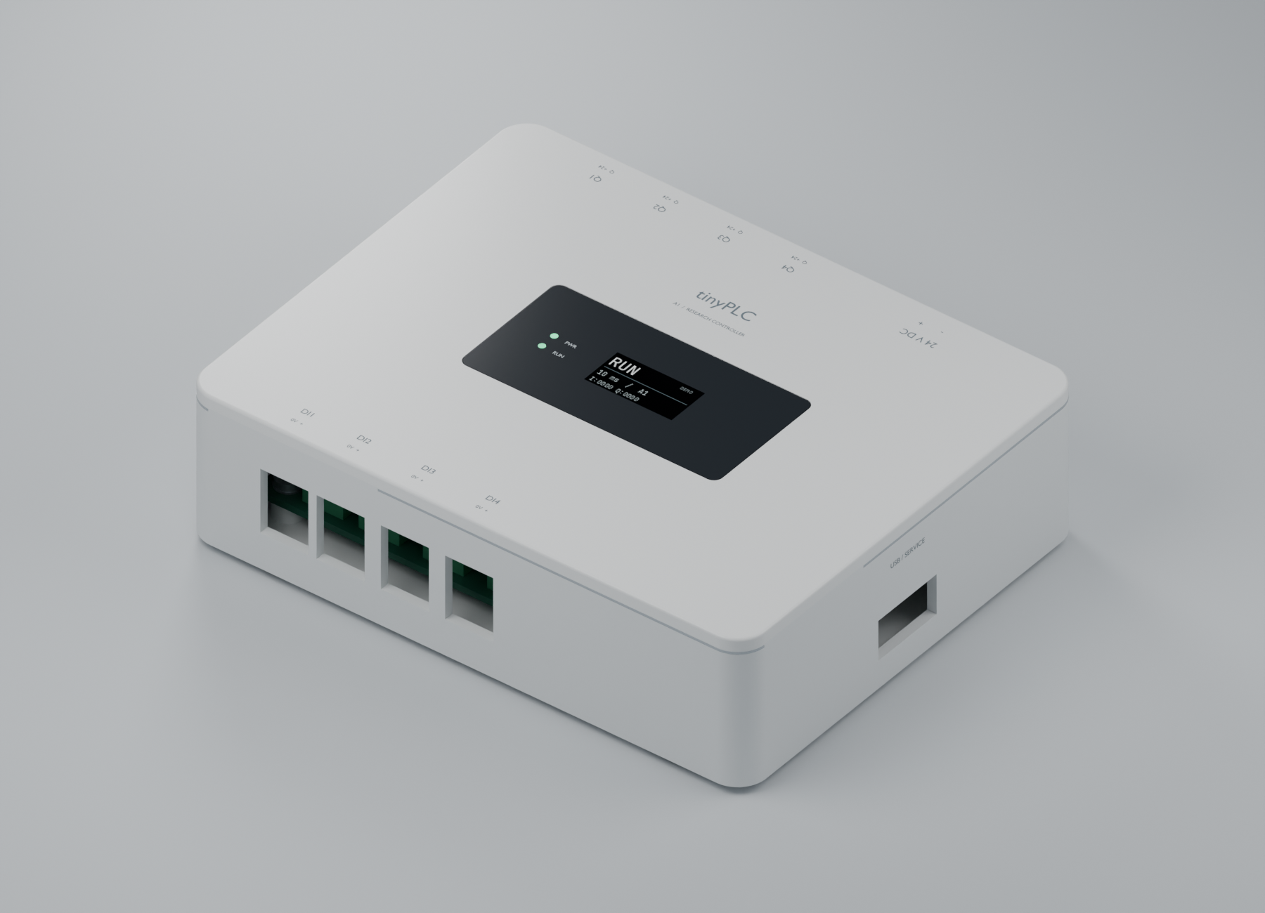
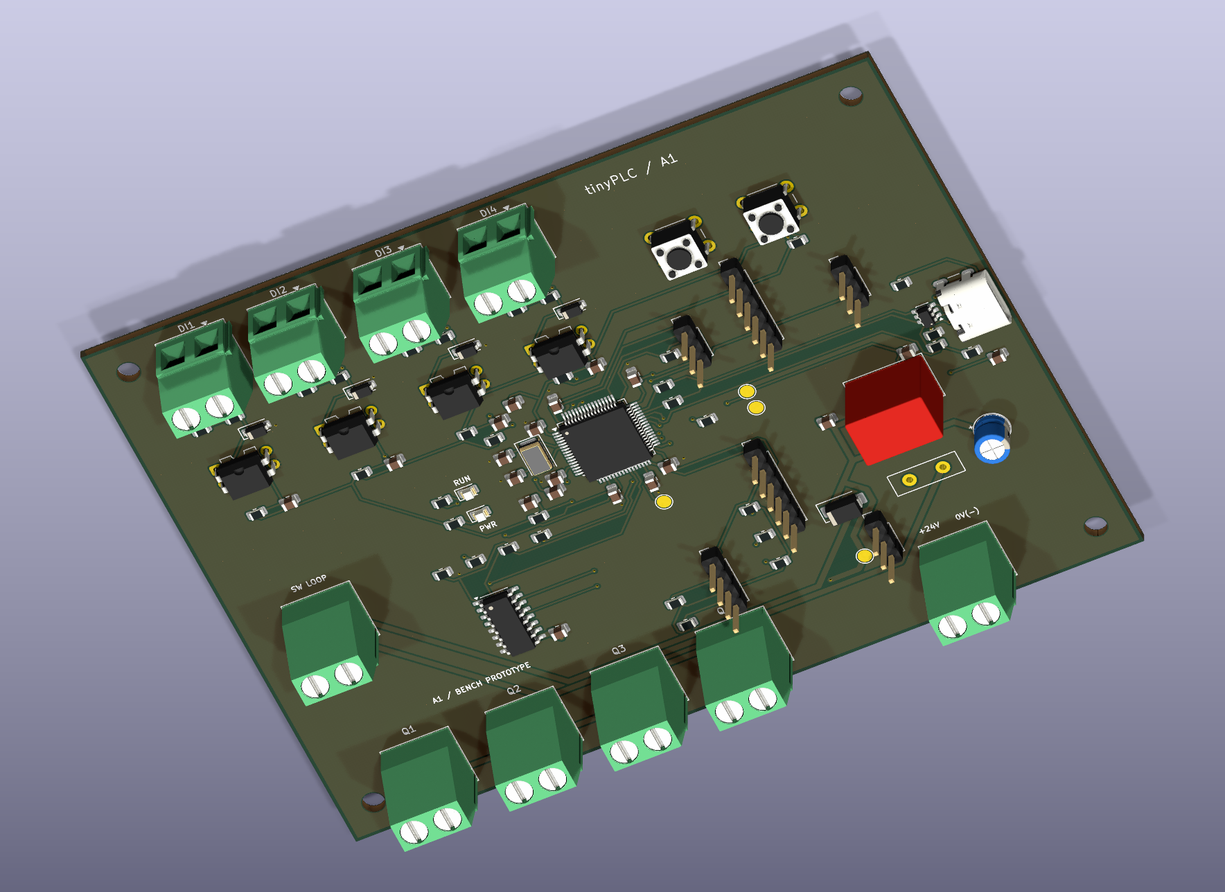
The enclosure is a Blender render; the board view comes from the routed KiCad design. The display shows a proposed demo UI. Rear connector view.
Implemented: a dependency-free Rust ST frontend, positioned diagnostics,
separate typed PLC IR, textual LLVM IR emission, exported tag metadata, and a
C-compatible scan entry point. Tests verify IR, execute host machine code at
-O0 and -O2, compare results with independent historical interpreters, and
cross-compile to ARM Cortex-M object code. A static FreeRTOS task now runs
linked ST machine code from RAM on the F446, samples PC13, commits PA5, latches
faults and measures the 10 ms release schedule. ST now executes in a separate
unprivileged task, with checked return, MPU isolation, TIM2 deadline abort and
IWDG reset fallback. R2 is complete; see the consolidated report.
The R3.1 wire contract now defines native packages and engineering frames, with generated Rust/C constants and golden fixtures.
R3.2 adds the Rust native packager and portable C package validation/staging, tested together on the host.
R3.3 connects the board over USB serial: plctool downloads
into an inactive slot, explicitly activates a generation, and reports execution
status. Downloaded code runs unprivileged with validated tag bindings and a
fresh worker context. Both slots and 64-tag execution have hardware evidence.
R3.4 adds owned snapshots and plctool DEVICE monitor,
with host concurrency tests and target build validation.
R3.5 verifies the full board workflow and mixed download/monitor
traffic: a 4.054 ms maximum observed scan body within the 10 ms period, with no
missed releases in the recorded run. R3 is complete.
R4 adds compatible VAR migration, a reserved first-scan trial and one-use rollback to saved pre-update state. Board evidence covers 64-tag reorder, contained faults, recovery failure and reset behavior.
R5.1 adds native TON on-delay timers and millisecond TIME values, with frozen clock input and explicit restart behavior for online changes. See the example and acceptance report.
Not implemented yet: tag writes, persistence or broader language types.
The primary compiler is compiler/ (Rust). Earlier Python/bytecode work is
retained only as a historical semantic test reference; it is not the product
architecture or a planned fallback execution mode.
Use existing Rust/Cargo, LLVM (clang, llvm-as, opt), Python 3.11+, CMake,
a C compiler, and ARM GNU ld for the package integration tests. No packages are fetched by these commands.
make compiler
./target/debug/plcc examples/button_led.st -o /tmp/button_led.ll
make run
make aot-arm
make test
make run compiles the example through Rust and LLVM, links it with a C host
harness, and prints R1 AOT scans=5 LED=1 N=2. make aot-arm creates
build/aot/button_led.arm.o, an ARM relocatable object. It does not upload,
link firmware, or flash a board. Compiler usage and ABI
and setup give exact reproduction commands.
The NUCLEO-F446RE must already have the current R5.1 runtime firmware installed through ST-LINK. Firmware prerequisites and build instructions are in setup and the target toolchain guide. The following workflow uploads an ST program through the ST-LINK virtual serial port; it does not replace the runtime firmware.
After a board reset, the boot program occupies slot A and slot B is available. Use your actual serial device path and installed toolchain paths:
make compiler
mkdir -p build/programs
PLC_DEVICE=/dev/cu.usbmodem2103
./target/debug/plctool "$PLC_DEVICE" info
./target/debug/plcpack examples/ton_led.st --slot B -o build/programs/ton-b.tplc \
  --clang /path/to/clang --ld /path/to/arm-none-eabi-ld
./target/debug/plctool "$PLC_DEVICE" download build/programs/ton-b.tplc
plcpack compiles ST, generates ARM code, links for the chosen slot, and builds
the download package. Download returns a JSON ready_generation; substitute
that number for GENERATION below:
./target/debug/plctool "$PLC_DEVICE" activate GENERATION
./target/debug/plctool "$PLC_DEVICE" status
./target/debug/plctool "$PLC_DEVICE" monitor
./target/debug/plctool "$PLC_DEVICE" update-status
Activation starts execution on the board's 10 ms scan cycle. In this example,
hold BTN for 500 ms to light LED; releasing BTN clears the timer and LED on the
next invocation. monitor prints one coherent snapshot, including TON Q/ET
and the clock; run it again for another sample. TIME values are milliseconds.
For subsequent edits, inspect info and build for the inactive slot: A is
0x20010000, B is 0x20014000, and ACTIVE has state 1. The download command
rejects a package built for the wrong available slot. Downloading only stages
code; activate is required to run it. See package usage
and engineering commands for details.
Healthy online updates preserve matching scalar VAR names/types. TON instances
restart their delays. plctool "$PLC_DEVICE" rollback restores the saved previous
program and scalar state when a checkpoint is available; timers restart again.
Starting another download retires that checkpoint. Downloads and state are
RAM-only: reset or power loss returns to the firmware's boot program.
flowchart TB
  subgraph PC["PC — frontend and AOT code generation implemented"]
    ST["ST source<br/>IEC 61131-3 subset"] --> Front["Rust frontend<br/>lexer, parser, semantic checks"]
    Front --> IR["Typed PLC IR<br/>tags, types, expressions, control flow"]
    IR --> LLVM["LLVM IR"]
    LLVM --> Object["LLVM ahead-of-time compiler<br/>ARM Cortex-M object code"]
    Object --> Experiment["Boot program<br/>static firmware link into slot A"]
    Experiment --> Runtime
    Object --> Link["Host link for slot A or B<br/>all addresses resolved on PC"]
    Link --> Package["Rust plcpack<br/>ABI, state layout, code, integrity metadata"]
  end
  Package -->|"plctool over ST-LINK USB serial"| Loader
  subgraph Board["STM32 — isolated native scan experiment implemented"]
    Loader["Low-priority C comms and loader<br/>validate, stage and seal inactive slot"]
    Loader --> Activate["Accept generation at scan boundary<br/>prepare state and protection context"]
    Activate --> Runtime["C supervisor on FreeRTOS<br/>periodically invokes native entry"]
    Runtime --> Worker["Unprivileged ST worker<br/>private stack and MPU permissions"]
    Worker --> Gate["Firmware-flash return gateway<br/>TIM2 deadline and watchdog fallback"]
    Gate --> Runtime
    Runtime --> IO["Input sampling and output commit"]
    Runtime --> Tags["Runtime-owned schema and values<br/>validated bindings, frozen I/O"]
    Tags --> Monitor["Coherent tag snapshots<br/>PC monitoring"]
  end
classDef implemented fill:#e1f5ef,stroke:#39927d,color:#064f43;Green is implemented; the R3.4 report distinguishes host tests from board evidence. The C
runtime is firmware installed through ST-LINK. The user program is a separate
native artifact downloaded through the engineering connection. A general
Linux .so or an unqualified raw .bin is not our MCU loading contract.
Full target design. Scheduling, sampled inputs, working/committed state, physical outputs, fault latching, unprivileged execution and native deadline abort are implemented in the scan supervisor and execution boundary. Owned tag snapshots are implemented in R3.4; tag-write boundary requests remain planned.
flowchart TB
  subgraph Scan["C scan supervisor — highest application priority"]
    Read["Sample physical inputs<br/>freeze input image"] --> Working["Prepare working state<br/>arm deadline guard"]
    Working --> Run["Invoke compiled native logic<br/>bounded unprivileged execution"]
    Run --> Check["Trusted return or abort<br/>commit success / discard failed work"]
    Check --> Outputs["Apply physical outputs<br/>FALSE on fault"]
    Outputs --> Publish["Publish coherent snapshot<br/>tags, scan ID, generation, diagnostics"]
    Publish --> Boundary["Apply accepted boundary request<br/>then wait for next release"]
    Boundary --> Read
  end
  subgraph Comms["Lower-priority engineering task"]
    Receive["Receive command"] --> Stage["Stage native image<br/>validate before READY"]
    Receive --> Request["Request activation/rollback<br/>bounded payload + generation"]
    Receive --> Monitor["Read owned snapshot<br/>respond to PC monitor"]
  end
  Request -. "scan owner applies" .-> Boundary
  Publish -. "three-buffer ownership mailbox" .-> Monitor
  Working -. "independent guard interrupts a stuck program" .-> Abort["Abort user context<br/>output policy + fault recovery"]
Comms never reads a tag by racing a live write or retaining a pointer into a reusable program slot. A snapshot contains values and names/types/scan and generation identifiers. A slow monitor may miss scans without blocking the producer. Tag writes remain unimplemented; the planned design routes them through the scan owner.
Native code addresses fields relative to a supplied state block. The symbol
metadata maps names to types/classes and offsets; it does not embed arbitrary
addresses in privileged runtime memory. Inputs are frozen and outputs are
proposals until commit. The initial research ABI uses one u32 cell per tag,
with byte offset 4 × declaration index.
Implemented download/activation workflow. Download success and activation success are separate states; R3.4 adds coherent tag snapshots.
sequenceDiagram
  actor User as Engineer
  participant PC as Rust frontend + LLVM + engineering CLI
  participant Loader as C loader / comms
  participant Scan as FreeRTOS scan supervisor
  User->>PC: Edit ST and build target native image
  PC->>Loader: Transfer bounded chunks
  Loader->>Loader: Validate package, ABI, exact slot and state schema
  Loader-->>PC: READY with candidate generation
  Note over Loader,Scan: Current program keeps running
  User->>PC: Accept edit
  PC->>Loader: ACTIVATE(candidate generation)
  Loader-->>PC: Request accepted, not yet running
  Loader->>Scan: Publish owned boundary request
  Scan->>Scan: Migrate compatible VARs and install a fresh native worker
  Scan->>Scan: Execute first candidate scan under deadline guard
  alt Successful execution
    Scan-->>Loader: Snapshot confirms running generation
  else Contained application fault
    Scan->>Scan: Outputs FALSE, discard candidate working state
    Scan->>Scan: Restore healthy checkpoint at the next release, if available
    Scan-->>Loader: Fault and rejected generation retained
  end
  PC->>Loader: Read execution status
  Loader-->>PC: Actual generation, outcome, fault and timing
  PC-->>User: Confirm the edit outcome
R4 migration matches exact internal variable names and types. Explicit rollback restores saved pre-update values and consumes its checkpoint. Inputs are resampled and outputs recomputed. Preserved variables do not promise unchanged output behavior; rollback cannot undo physical actions. Two slots cannot preserve active, previous, and another candidate at once. Slot reservations and generation checks are required; a pending flag and pointer flip alone are insufficient.
The initial language is a small IEC 61131-3-inspired ST subset, not full IEC conformance: BOOL, DINT, TIME, input/output/internal declarations, assignments, IF/ELSIF/ELSE, DINT arithmetic, comparisons, eager boolean logic, comments, and TON on-delay timers with IN/PT inputs and Q/ET outputs. TIME supports nonnegative millisecond durations and comparisons, not arithmetic. See language.md and TON for exact grammar, clock behavior, and limits: 64 expanded cells, including five per timer and one shared clock cell. General function blocks and loops are not supported.
PROGRAM Main
VAR_INPUT BTN : BOOL; END_VAR
VAR_OUTPUT LED : BOOL; END_VAR
VAR n : DINT; END_VAR
IF BTN THEN n := n + 1; END_IF;
LED := NOT BTN;
END_PROGRAM
N increments on every scan with BTN pressed, not once per press. DINT wraps
modulo 2^32. Division by zero reports a fault; minimum DINT divided by -1 wraps.
The Rust emitter preserves these rules explicitly instead of relying on LLVM
undefined behavior. LLVM division semantics.
The NUCLEO-F446RE contains an STM32F446RE Cortex-M4F, an onboard ST-LINK/V2-1 debugger, a user LED, and a user button. Connect a USB data cable to ST-LINK CN1. No external I/O circuitry is needed for the first example. This board provides 3.3 V logic; industrial 24 V inputs and outputs would need separate conditioning and protection hardware.
| Resource | Project mapping | Verification and qualification |
|---|---|---|
| LD2 green user LED | LED → PA5, HIGH lights it | UM1724 §7.6 and Table 19 |
| B1 user button | BTN → PC13, inverted for pressed = TRUE | UM1724 §7.7 confirms pin; polarity must match board schematic/revision before hardware acceptance |
| ST-LINK virtual COM port | USART2: PA2 TX, PA3 RX | UM1724 §7.10, default solder bridges SB13/SB14 connected |
| Serial configuration | 115200 baud, 8 data bits, no parity, 1 stop bit | Chosen firmware setting, not a fixed hardware setting |
| Memory | 512 KB flash, 128 KB main SRAM | STM32F446xC/E datasheet; also 4 KB backup SRAM, unused in v1 |
| Ethernet | No onboard Ethernet interface | Use UART on the board; host TCP transport is planned |
On macOS a VCP commonly appears as /dev/tty.usbmodem* and /dev/cu.usbmodem*; discover the actual path rather than hardcoding it. A detected device does not prove the firmware works. The hardware references are ST UM1724 Rev 17, STM32F446 datasheet, and MB1136 C04 schematic, MCU sheet. The requested facts are consistent with these qualifications: baud and Mac device path are configuration/environment choices, and 128 KB excludes backup SRAM.
The Rust CLI currently uses built-in logical bindings for BTN (BOOL input)
and LED (BOOL output). The board profile records
the physical mapping; the C board port applies it. The compiler library
also accepts an explicit list of logical bindings. No register access is emitted
into user logic.
See the educational design and compiler/runtime studies for the reading order, dependency boundary, and reasons for using a small STM32 board.
| Directory | Role |
|---|---|
compiler/ | Primary Rust lexer/parser, semantic analysis, typed PLC IR, LLVM emitter, CLI, scan ABI, tests |
contract/ | Shared wire definitions and generated Rust/C constants |
packager/, engineering/ | Rust native package builder and serial engineering CLI |
runtime/ | Portable C scan transaction, package validator, staging and framing |
sim/aot_main.c | Current C harness invoking host AOT machine code |
port/ | STM32 C/FreeRTOS supervisor, GPIO/UART, MPU, deadline and fault handling; historical blink |
tests/llvm/ | IR verification, optimized host AOT execution, ARM codegen and semantic comparisons |
boards/ | Explicit target I/O mapping; native profiles are documented in docs/ |
core/, host/, tests/native/ | Historical M1/M2 implementation and independent test oracles |
docs/ | Current architecture, compiler contract, native loader roadmap, reports and historical designs |
The Rust frontend uses only its standard library. LLVM is a PC-side toolchain dependency; no LLVM library or compiler runs on the MCU. FreeRTOS is the scheduler dependency. The project owns PLC semantics, the native image/ABI contract, engineering operations, and runtime state management.
| Stage | Deliverable | Status |
|---|---|---|
| M0–M2 | Initial board scaffold, C VM, Python compiler and independent execution tests | Historical; retained for evidence and test reuse |
| R1 | Rust ST frontend → typed PLC IR → LLVM IR; host AOT and Cortex-M object generation | Implemented and host-tested |
| R2 | Native ABI/package contract, C supervisor, bounded static native execution and fault containment on F446 | Complete, including hardware evidence |
| R3 | Native loader, upload protocol, engineering CLI and coherent tag monitoring | Complete, including board monitoring and mixed-traffic timing |
| R4 | Online state migration, first-scan trial and explicit/automatic rollback | Implemented and verified on the board |
| R5.1 | TON on-delay timers, TIME, frozen clock input and restart-on-update behavior | Complete, including host and board acceptance |
| Further R5 work | Additional language features, source debugging, persistence and target ports | Future extensions |
R1 replaces the earlier bytecode-first roadmap. No MCU loading, RTOS timing, or hardware acceptance is implied by host tests. Runtime architecture explains ownership and recovery; native roadmap compares the learning project with a production prototype and specifies target acceptance gates. M1 and M2 remain dated records, not current implementation instructions. Project code is MIT licensed.
The educational approach is inspired by Andrej Karpathy's micrograd and nanoGPT. We study Rusty, OpenPLC Runtime and matiec for compiler/runtime design lessons. tinyplc remains an independent implementation with its own small scope and contracts. See references and acknowledgments for credits, official Rust/C/LLVM/FreeRTOS/STM32 documentation, and the attribution policy.
The task checklist records completed work, acceptance evidence
and open decisions. R1 and the R2.1 target call ABI draft are complete.
The compiler supports --abi 2; the ST example now runs from RAM in a
FreeRTOS board experiment with an unprivileged native worker. R2.2 toolchain and MPU-port selection is
recorded; R2.3 and R2.4 now include hardware evidence.
R2.3 now has a buildable FreeRTOS layout scaffold and checked ELF memory boundaries. Its privileged supervisor schedules LLVM-generated ST with physical input/output supervision; R2.5 records GPIO, fault-latch and scan-timing evidence. R2.6 adds unprivileged protection, checked return/abort and watchdog recovery. Package requirements and fixed-slot placement are defined in R2.7. The R2 report closes this stage. R3.1 freezes shared package/protocol encoding and golden fixtures. R3.2 adds the Rust packager and bounded C validation/staging. R3.3 implements USB serial download and board activation. R3.4 implements coherent tag snapshots and PC monitoring. R3.5 closes the board workflow and timing gate. R4.1 defines migration, initialization and rollback state semantics. R4.2 implements them and R4.3 records board acceptance. R5.1 adds verified TON/TIME support. Further extensions remain future work, selected from a documented need.
| Qty | Value | Footprint | References |
|---|---|---|---|
| 11 | 10k | tinyplc:R_0805_2012Metric | R2, R3, R4, R5, R12, R22, R32, R42, R70, R71, R72 |
| 9 | 100nF / 50V | tinyplc:C_0805_2012Metric | C2, C4, C5, C6, C7, C10, C12, C30, C31 |
| 8 | 2.2k | tinyplc:R_0805_2012Metric | R10, R11, R20, R21, R30, R31, R40, R41 |
| 5 | 100k | tinyplc:R_0805_2012Metric | R51, R52, R53, R54, R65 |
| 4 | 10nF / 50V | tinyplc:C_0805_2012Metric | C21, C22, C23, C24 |
| 4 | 1N4148W | tinyplc:D_SOD-123 | D11, D12, D13, D14 |
| 4 | M3 NPTH | tinyplc:MountingHole_3.2mm_M3 | H1, H2, H3, H4 |
| 4 | VO617A-3 | tinyplc:DIP-4_W7.62mm | U4, U5, U6, U7 |
| 3 | 22 | tinyplc:R_0805_2012Metric | R1, R62, R63 |
| 2 | 27pF C0G / 50V | tinyplc:C_0805_2012Metric | C13, C14 |
| 2 | 4.7k | tinyplc:R_0805_2012Metric | R73, R74 |
| 2 | 4.7uF / 10V | tinyplc:C_0805_2012Metric | C8, C9 |
| 2 | 5.1k | tinyplc:R_0805_2012Metric | R60, R61 |
| 1 | +24 / Q1 sink | tinyplc:TerminalBlock_Phoenix_MKDS-1,5-2-5.08_1x02_P5.08mm_Horizontal | J9 |
| 1 | +24 / Q2 sink | tinyplc:TerminalBlock_Phoenix_MKDS-1,5-2-5.08_1x02_P5.08mm_Horizontal | J10 |
| 1 | +24 / Q3 sink | tinyplc:TerminalBlock_Phoenix_MKDS-1,5-2-5.08_1x02_P5.08mm_Horizontal | J11 |
| 1 | +24 / Q4 sink | tinyplc:TerminalBlock_Phoenix_MKDS-1,5-2-5.08_1x02_P5.08mm_Horizontal | J12 |
| 1 | +3V3 | tinyplc:TestPoint_Pad_D2.0mm | TP2 |
| 1 | 10uF / 10V | tinyplc:C_0805_2012Metric | C3 |
| 1 | 1k | tinyplc:R_0805_2012Metric | R6 |
| 1 | 1uF / 10V | tinyplc:C_0805_2012Metric | C11 |
| 1 | 22uF / 50V | tinyplc:CP_Radial_D6.3mm_P2.50mm | C1 |
| 1 | 24V IN / GND | tinyplc:TerminalBlock_Phoenix_MKDS-1,5-2-5.08_1x02_P5.08mm_Horizontal | J1 |
| 1 | 500mA / 60V | tinyplc:PTC_MF_R050 | F1 |
| 1 | 68k | tinyplc:R_0805_2012Metric | R64 |
| 1 | 8MHz CL18pF | tinyplc:Crystal_SMD_5032-2Pin_5.0x3.2mm | Y1 |
| 1 | BOOT: 1=3V3 2=BOOT0 3=GND | tinyplc:PinHeader_1x03_P2.54mm_Vertical | J2 |
| 1 | DI1 / GND | tinyplc:TerminalBlock_Phoenix_MKDS-1,5-2-5.08_1x02_P5.08mm_Horizontal | J5 |
| 1 | DI2 / GND | tinyplc:TerminalBlock_Phoenix_MKDS-1,5-2-5.08_1x02_P5.08mm_Horizontal | J6 |
| 1 | DI3 / GND | tinyplc:TerminalBlock_Phoenix_MKDS-1,5-2-5.08_1x02_P5.08mm_Horizontal | J7 |
| 1 | DI4 / GND | tinyplc:TerminalBlock_Phoenix_MKDS-1,5-2-5.08_1x02_P5.08mm_Horizontal | J8 |
| 1 | ETH: GND RST INT | tinyplc:PinHeader_1x03_P2.54mm_Vertical | J15 |
| 1 | GND | tinyplc:TestPoint_Pad_D2.0mm | TP1 |
| 1 | GREEN | tinyplc:LED_0805_2012Metric | D2 |
| 1 | OLED: 3V3 GND SCL SDA | tinyplc:PinHeader_1x04_P2.54mm_Vertical | J16 |
| 1 | RESET | tinyplc:SW_PUSH_6mm | SW1 |
| 1 | SPI: 3V3 GND SCK MISO MOSI CS | tinyplc:PinHeader_1x06_P2.54mm_Vertical | J14 |
| 1 | SS16 | tinyplc:D_SMA | D1 |
| 1 | STM32F446RET6 | tinyplc:LQFP-64_10x10mm_P0.5mm | U1 |
| 1 | SWD: 3V3 GND DIO CLK NRST SWO | tinyplc:PinHeader_1x06_P2.54mm_Vertical | J3 |
| 1 | TPL7407LDR | tinyplc:SOIC-16_3.9x9.9mm_P1.27mm | U3 |
| 1 | TSR 1-2433 | tinyplc:Converter_DCDC_TRACO_TSR-1_THT | U2 |
| 1 | UART: GND TX RX | tinyplc:PinHeader_1x03_P2.54mm_Vertical | J4 |
| 1 | USB-C DEVICE | tinyplc:USB_C_Receptacle_GCT_USB4105-xx-A_16P_TopMnt_Horizontal | J13 |
| 1 | USBLC6-2SC6 | tinyplc:SOT-23-6 | U8 |
| 1 | USER | tinyplc:SW_PUSH_6mm | SW2 |
| 1 | V24 | tinyplc:TestPoint_Pad_D2.0mm | TP3 |
| 1 | VCAP1 | tinyplc:TestPoint_Pad_D2.0mm | TP4 |
It measures 120 × 90 mm and has 2 copper layers, 1.6 mm thick.
95 parts, built around the STM32F446RET6, VO617A-3, USBLC6-2SC6 and 1N4148W. The full list of its parts is on this page, with links to each part's symbol and footprint where PCBKit's library has them.
From the sergiogallegos/tinyplc repository on GitHub, at the commit this page was made from: the board is hardware/prototype-a/electronics/tinyplc-a0.kicad_pcb and its schematic hardware/prototype-a/electronics/tinyplc-a0.kicad_sch. PCBKit opens the board in the browser, with nothing to install.
Its repository publishes it under the MIT licence: you may reuse it on that licence's terms (keep the author's notice, and for a copyleft licence share your changes alike).

OpenParol/OpenParol-Board
Open-source project for a 6-DOF robotic arm controller


porast1/suspension-telemetry
Suspension telemetry system for mountain bike or dirt bike


