


2 layers100 × 80 mm
Meganecan gw
Barbedx/MeganeCAN
ESP32-based CAN-bus companion for Renault Megane 2 infotainment displays.
68 parts3

A custom Raspberry Pi 4 Model B HAT designed for image capture, processing, and display using an ArduCAM OV2640 camera, ST7735 TFT display, and an LM2596S-3.3 based switching power supply.
HAT RP is an open-source printed circuit board by senadurarslan, from the senadurarslan/Raspberry-Pi-Image-Processing-HAT repository on GitHub. It is a 2-layer board of 65 × 56 mm with 20 parts on 35 nets, routed with 73 tracks and 9 vias.
It is built around the LM2596S-3.3 and SS34. Its parts include 4 capacitors, 4 resistors, 3 diodes, 3 connectors and 1 IC.
A custom Raspberry Pi 4 Model B HAT designed for image capture, processing, and display using an ArduCAM OV2640 camera, ST7735 TFT display, and an LM2596S-3.3 based switching power supply.
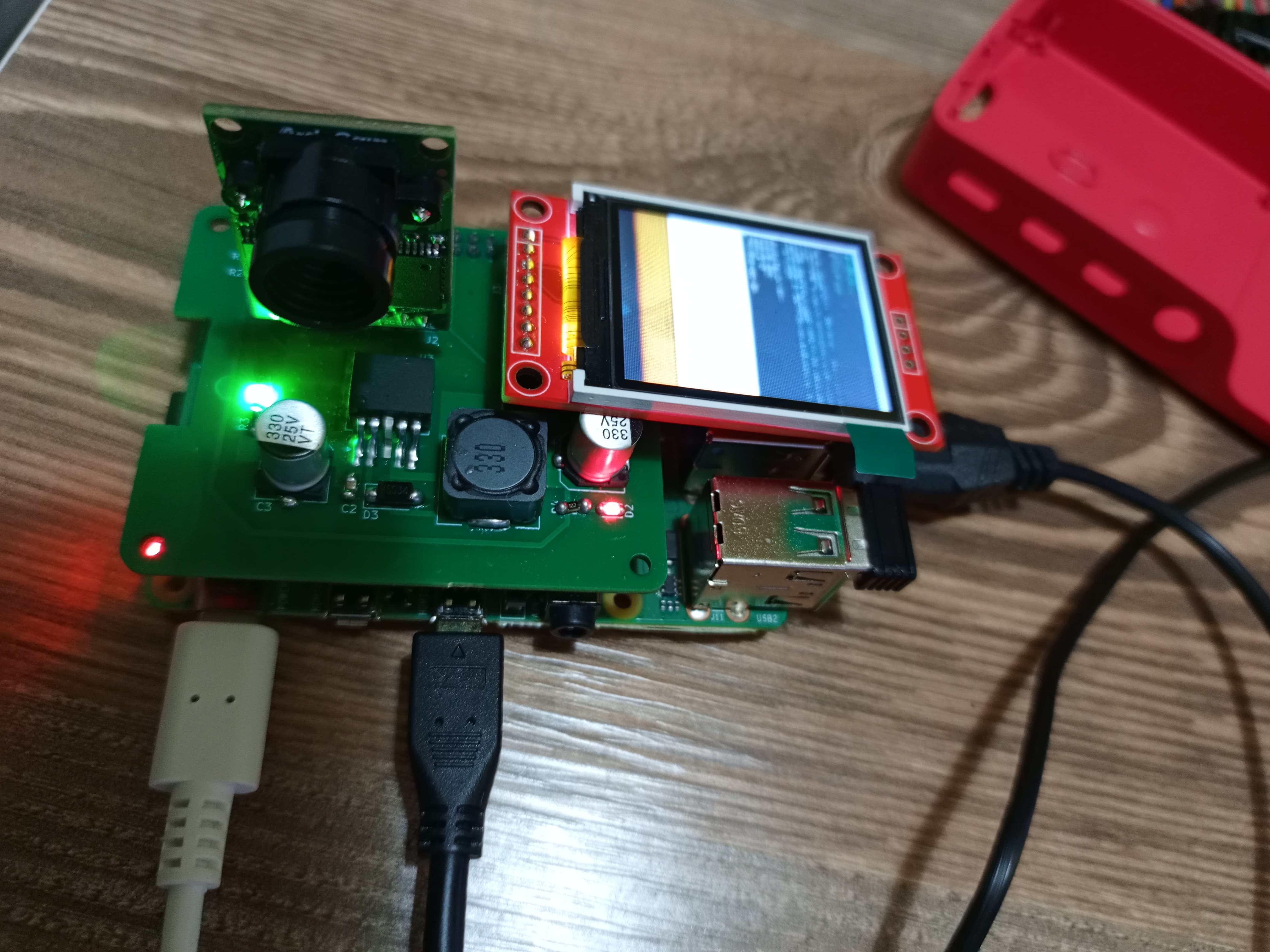
This project focuses on the design and implementation of a custom Hardware Attached on Top (HAT) board for the Raspberry Pi 4 Model B.
The system captures images using an ArduCAM OV2640 camera, processes the image data on the Raspberry Pi, and displays the resulting output on an ST7735 TFT display.
A custom PCB was designed to integrate the camera, display, Raspberry Pi GPIO interface, and power management circuitry into a compact embedded vision platform.
The main hardware blocks are:
The Raspberry Pi acts as the main processing and control unit.
The ArduCAM OV2640 communicates with the Raspberry Pi using:
The ST7735 TFT display uses:
The overall image processing flow is:
        ArduCAM OV2640
              │
       ┌──────┴──────┐
       │             │
      I²C           SPI
Configuration    Image Data
       │             │
       └──────┬──────┘
              ▼
       Raspberry Pi 4
              │
       JPEG Acquisition
              │
       Buffer Processing
              │
        JPEG Decoding
              │
       RGB565 Conversion
              │
              ▼
ST7735 TFT DisplayThe custom HAT PCB was designed using KiCad EDA.
The hardware design includes:
The PCB was designed as a two-layer board and manufactured using the generated Gerber files.
After production, the components were assembled and the board was mounted directly onto the Raspberry Pi for functional testing.
An LM2596S-3.3 based switching power supply (SMPS) was integrated into the HAT design.
The power stage converts the available supply voltage to the required 3.3 V rail for the peripheral hardware.
A switching regulator was preferred to provide:
The software was developed using C and C++ on Raspberry Pi OS.
The implementation includes:
arduchip.c
arduchip.h

ov2640.c
ov2640.h
ov2640_regs.c
ov2640_regs.h

spi_linux.c
spi_linux.h

i2c_linux.c
i2c_linux.h

jpeg_to_rgb565.c
jpeg_to_rgb565.h

capture_to_file.c
capture_to_screen.cpp
decode_test.c

test_arduchip.c
test_hal.cThe project includes a Makefile for compiling and running the camera, image processing, and TFT applications.
The project uses:
gcc
g++
The full camera-to-display application is compiled using:
-std=gnu++20The TFT application uses:
rpidisplaygl
lgpio
librt
with:
/usr/local/include
/usr/local/libmakeThe default target displays the available build and run commands.
make cleanThis removes generated object files, executables, and temporary image files such as:
frame.jpg
frame.rgb565Compile:
make test_arduchipRun:
make run_test_arduchipThis test verifies communication with the ArduChip interface.
Compile:
make test_halRun:
make run_test_halThis test verifies OV2640 initialization and communication through the hardware abstraction layer.
Compile:
make capture_appRun:
make run_capture_appThe application captures an image from the OV2640 camera and stores the acquired JPEG data.
Compile:
make decode_testRun:
make run_decode_testThis application tests the conversion of captured JPEG image data into the RGB565 pixel format used by the TFT display.
Compile:
make capture_screenRun:
make run_capture_screenThis application combines the complete image pipeline:
Camera
  ↓
JPEG Capture
  ↓
Image Processing
  ↓
RGB565 Conversion
  ↓
ST7735 TFTThe final implementation combines the custom HAT PCB, ArduCAM OV2640 camera, ST7735 TFT display, onboard power stage, and Raspberry Pi into a single integrated system.
The OV2640 camera was configured and tested on the Raspberry Pi.
Image data captured from the camera was transferred to the Raspberry Pi and successfully stored as a JPEG image.
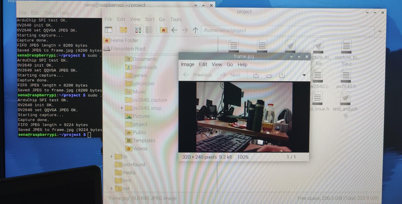
The terminal output verifies the camera communication and image acquisition process, including:
ArduChip SPI test OK
OV2640 init OK
Starting capture...
Capture done
Saved JPEG to frame.jpgThe image captured by the OV2640 camera was processed by the Raspberry Pi and displayed on the ST7735 TFT.
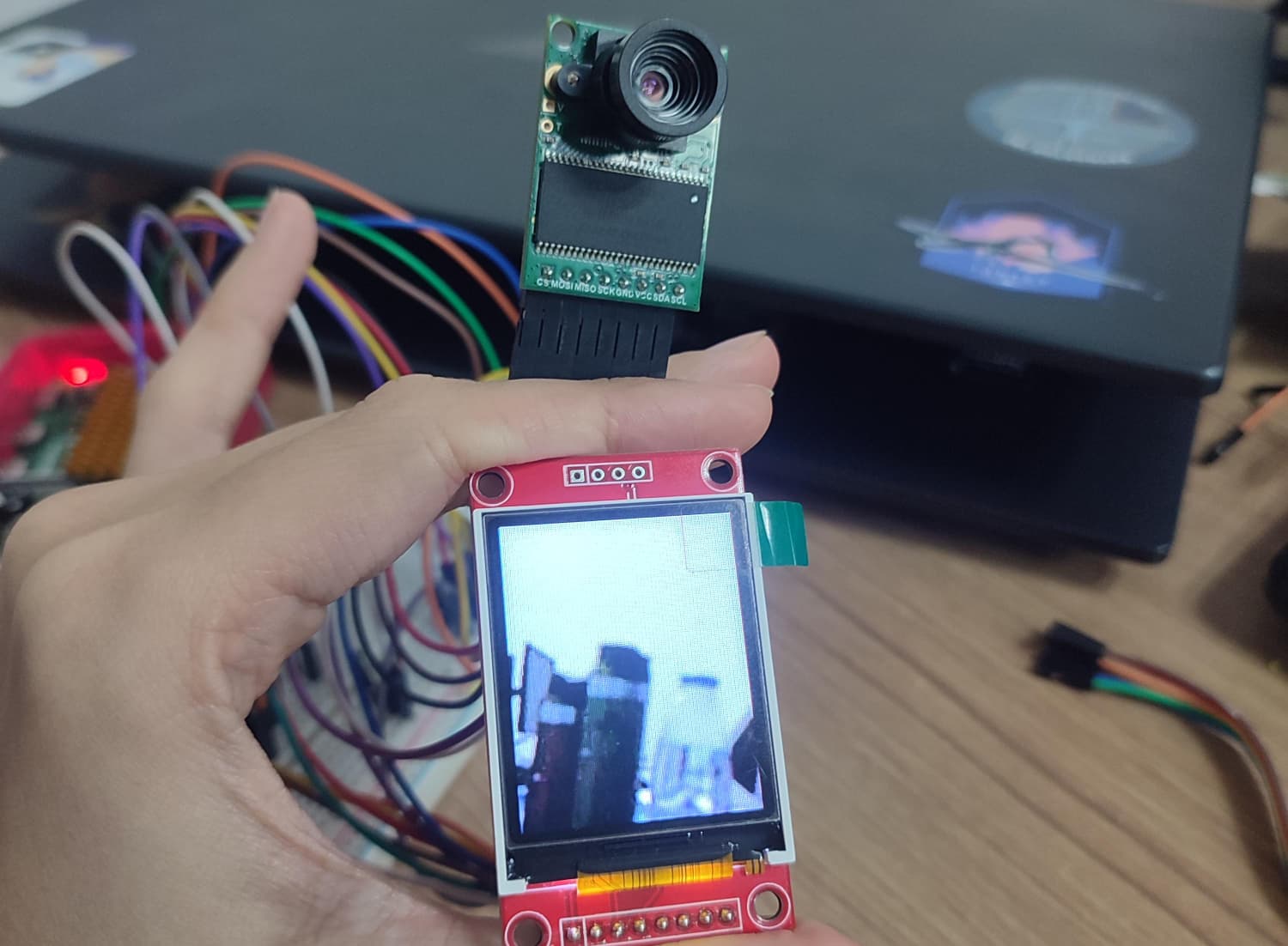
This test demonstrates the complete image pipeline from camera acquisition to TFT visualization.
The system was tested incrementally before full integration.
The main test stages included:
The final system successfully captured image data from the OV2640 camera, processed the image on the Raspberry Pi, and displayed the resulting image on the ST7735 TFT.
The PCB development process consisted of:
System Requirements
        ↓
Component Selection
        ↓
Schematic Design
        ↓
PCB Layout
        ↓
Gerber Generation
        ↓
PCB Manufacturing
        ↓
Component Assembly
        ↓
Electrical Testing
        ↓
Raspberry Pi Integration
        ↓
Functional Testing
The PCB design files and manufacturing outputs are included in the repository.
The repository contains:
Raspberry-Pi-Image-Processing-HAT/
│
├── images/
│   ├── final_hat_system.jpg
│   ├── camera_capture_test.jpeg
│   └── camera_tft_test.jpeg
│
├── KiCad/
│   └── PCB and schematic design files
│
├── mühtas_1_project/
│   ├── Camera drivers
│   ├── SPI / I²C drivers
│   ├── Image processing files
│   ├── TFT application
│   └── Makefile
│
├── rapor/
│   └── Project documentation and reports
│
└── README.mdDetailed project documentation, design reports, system requirements, and test procedures are available in the repository.
The project documentation covers:
This project was developed as part of the MÜHTAS-1 Engineering Design Project in the Department of Electronics and Communication Engineering at Kocaeli University.
The project combines embedded software development, digital communication interfaces, PCB design, power electronics, and image processing into a complete embedded vision system.
Sena Sümeyye Durarslan
Electronics and Communication Engineering
Kocaeli University
| Qty | Value | Footprint | References |
|---|---|---|---|
| 4 | MountingHole_2.7mm_M2.5 | MountingHole:MountingHole_2.7mm_M2.5 | MH1, MH2, MH3, MH4 |
| 2 | 100nF | Capacitor_SMD:C_0805_2012Metric | C2, C5 |
| 2 | 1k | Resistor_SMD:R_0805_2012Metric | R3, R4 |
| 2 | 330uF | Capacitor_SMD:CP_Elec_8x10 | C3, C4 |
| 2 | 4.7K | Resistor_SMD:R_0805_2012Metric | R1, R2 |
| 2 | Conn_01x08_Socket | Connector_PinSocket_2.54mm:PinSocket_1x08_P2.54mm_Vertical | J2, J3 |
| 2 | LED | LED_SMD:LED_0805_2012Metric | D1, D2 |
| 1 | 33uH | Inductor_SMD:L_12x12mm_H8mm | L1 |
| 1 | GPIO | Connector_PinSocket_2.54mm:PinSocket_2x20_P2.54mm_Vertical | J1 |
| 1 | LM2596S-3.3 | Package_TO_SOT_SMD:TO-263-4 | U3 |
| 1 | SS34 | Diode_SMD:D_SMA | D3 |
Barbedx/MeganeCAN
ESP32-based CAN-bus companion for Renault Megane 2 infotainment displays.

Circuit-Digest/machine-vision-robotic-assembly-system
A machine vision-based robotic assembly system using the MechArm 270, NVIDIA Jetson Nano, and a custom ESP32 controller board for automated pick-and-place and miniature car assembly.

Aryan-G4/PCBusiness_card
A pocket sized multimedia macropad, memory storage device, sd card reader, nRF devkit and bluetooth transceiver all in the size of a business card

bejaouihamza/CUSTOM_ROBOT_PCB_WITH_ESP32
Key Features 🚀 Core Components ESP32-C3-WROOM-2 – RISC-V-based MCU with WiFi 4 & Bluetooth 5 (BLE)


PA-33/gopro-control-station
Two-axis motorised GoPro mount with physical buttons, BLE camera control, and a built-in HTTPS web UI for live HDMI preview and gallery access. ESP32-S3 / SimpleFOC.

It measures 65 × 56 mm and has 2 copper layers, 1.6 mm thick.
20 parts, built around the LM2596S-3.3 and SS34. The full list of its parts is on this page, with links to each part's symbol and footprint where PCBKit's library has them.
From the senadurarslan/Raspberry-Pi-Image-Processing-HAT repository on GitHub, at the commit this page was made from: the board is KiCad/HAT_tas/HAT_RP/HAT_RP.kicad_pcb and its schematic KiCad/HAT_tas/HAT_RP/HAT_RP.kicad_sch. PCBKit opens the board in the browser, with nothing to install.
Its repository states no licence, so its author keeps all rights: ask senadurarslan before reusing the design.