
4 layers93.1 × 47.3 mm
MainPCB V3
selina101/CreateLabWork
Repo with projects done during my thesis and the valorisation.
74 parts

Repo with projects done during my thesis and the valorisation.
IMU6 is an open-source printed circuit board by selina101, from the selina101/CreateLabWork repository on GitHub. It is a 2-layer board with 15 parts on 15 nets, routed with 153 tracks and 9 vias.
Its parts include 4 resistors, 3 capacitors and 2 ICs.
In this repo you will find all the work done during the master thesis and during the master valorisation (02/2024-12/2024).
For the PCBs, you will find all the KiCAD files, as well as the gerber files to be able to order PCBs. The file 'PCB library' contains the footprint, the symbols and the 3D models of all the components used for all of the PCBs.
Contains the power distribution PCB for Max's robot.
All the components were bought separately and soldered by hand.
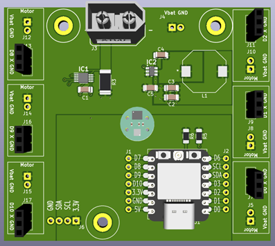
Contains two folders, one with the hall sensors and the other with the FSRs.
For all the Hall sensor PCBs, all the components were bought separately and soldered by hand.
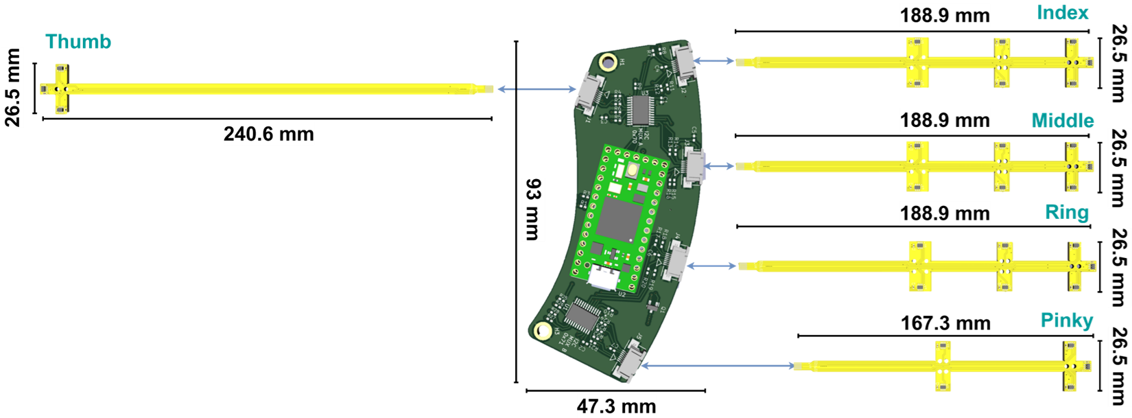
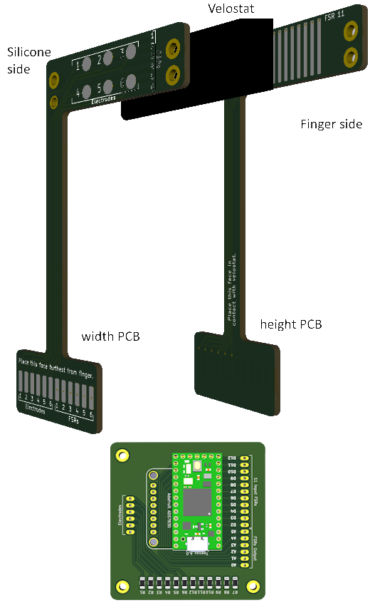
For the FSRs PCBs, there are no components to solder, one only needs to buy the PCBs and cut the velostat.
There is a main PCB that allows for connections. On this PCB, 1206 10kOhm pullup resistors are used, and need to be soldered by hand. If the electrodes are used for a hydrogel, a Adafruit ADS7830 Breakout board is needed.
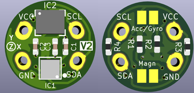
The IMU folder contains various versions of the IMU.
IMU_V2 is the round PCB that is used for the squid/tentacle projects. They are also the PCBs that need to be mounted on Max's PCB.
IMU_V3 is the sets of PCBs designed for the Helix type robot. There is the main PCBs that has the space for 2 perpendicular IMUs, the teensy and the I2C Qwiic connectors. There are also the files for the rectangular IMUs.
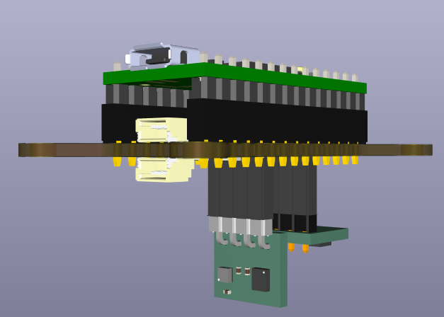
Both types are accompanied by a pdf explaining everything needed to know for the IMUs.
The IMUs are bought with the top side soldered on by JLCPCB. They have recently changed there classification of these sensors, so they must be bought in larger quantities and in panels because the PCBs are too small otherwise. The minimum quantity for the V3 was 45 IMUs. The back side of the PCBs must then be soldered by hand. For the main PCB, all the components were bought separately and soldered by hand.
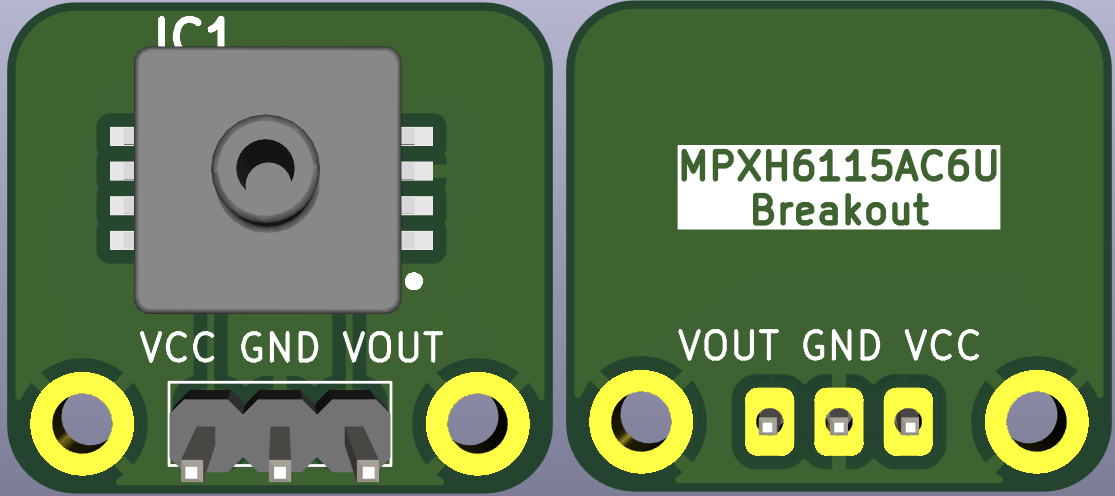
Contains the files for the PCBs that Kai asked for, it is a breakout for the MPXH6115AC6U pressure sensor.
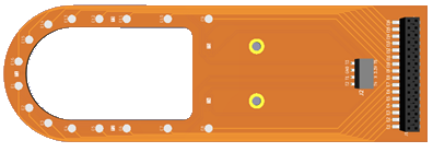
Contains the files for Benhui's Tongue PCB.
All the components were bought separately and soldered by hand.
| Qty | Value | Footprint | References |
|---|---|---|---|
| 4 | ~ | MasterThesis_library:THT_Small | 3.3V1, GND1, SCL1, SDA1 |
| 2 | 1.9k | Resistor_SMD:R_0402_1005Metric_Pad0.72x0.64mm_HandSolder | R3, R4 |
| 2 | 100 nF | Capacitor_SMD:C_0402_1005Metric_Pad0.74x0.62mm_HandSolder | C1, C2 |
| 2 | 10k | Resistor_SMD:R_0402_1005Metric_Pad0.72x0.64mm_HandSolder | R1, R2 |
| 2 | Jumper_2_Open | Jumper:SolderJumper-2_P1.3mm_Open_Pad1.0x1.5mm | JP1, JP2 |
| 1 | 1 uF | Capacitor_SMD:C_0402_1005Metric_Pad0.74x0.62mm_HandSolder | C3 |
| 1 | LIS3MDLTR | MasterThesis_library:LIS3MDLTR | IC1 |
| 1 | LSM6DSOXTR | MasterThesis_library:LSM6DSOXTR | IC2 |
15 parts. The full list of its parts is on this page, with links to each part's symbol and footprint where PCBKit's library has them.
From the selina101/CreateLabWork repository on GitHub, at the commit this page was made from: the board is IMU/IMU_V2/IMU6.kicad_pcb and its schematic Goat power PCB/Max_MainPCB/Max_MainPCB.kicad_sch. PCBKit opens the board in the browser, with nothing to install.
Its repository states no licence, so its author keeps all rights: ask selina101 before reusing the design.
selina101/CreateLabWork
Repo with projects done during my thesis and the valorisation.

selina101/CreateLabWork
Repo with projects done during my thesis and the valorisation.

selina101/CreateLabWork
Repo with projects done during my thesis and the valorisation.

selina101/CreateLabWork
Repo with projects done during my thesis and the valorisation.

selina101/CreateLabWork
Repo with projects done during my thesis and the valorisation.

selina101/CreateLabWork
Repo with projects done during my thesis and the valorisation.

selina101/CreateLabWork
Repo with projects done during my thesis and the valorisation.

selina101/CreateLabWork
Repo with projects done during my thesis and the valorisation.

selina101/CreateLabWork
Repo with projects done during my thesis and the valorisation.

selina101/CreateLabWork
Repo with projects done during my thesis and the valorisation.

selina101/CreateLabWork
Repo with projects done during my thesis and the valorisation.

google/mozc-devices
Circuit diagrams and firmware source code for Gboard DIY keyboards

hoglet67/RGBtoHDMI
Bare-metal Raspberry Pi project that provides pixel-perfect sampling of Retro Computer RGB/YUV video and conversion to HDMI

mntmn/amiga2000-gfxcard
MNT VA2000, an Open Source Amiga 2/3/4000 Graphics Card (Zorro II/III), written in Verilog

hackclub/OnBoard
💡 Join 1,000 teenagers and make your first PCB with a $100 grant!

kenp-io/not-for-airpods-repairs
The content of this repository is licensed under the WTFPL License. Please have a close look at the terms before using this material.

Luos-io/luos_engine
Open-source and real-time orchestrator for cyber-physical-systems, to easily design, test and deploy embedded applications and digital twins.

Chrismettal/EleLab_v2
Cheap DIY lab system for hobbyists and the tinkering folk
