2 layers

 sdp8483/base_convert3
handheld calculator to convert between hex, dec, and bin
Base convert is an open-source printed circuit board by sdp8483, from the sdp8483/base_convert repository on GitHub, published under the MIT licence. It is a 2-layer board of 93.3 × 100 mm with 98 parts on 111 nets, routed with 1,177 tracks and 136 vias.
It is built around the MSP430FR2033IPMR, MIC5317-3.3YM5-TR and LTD-2601WC, with the BIT3 among its other parts. Its parts include 27 transistors, 18 switches, 16 diodes, 4 capacitors and 2 resistors. It belongs with the MSP430 boards of this library.


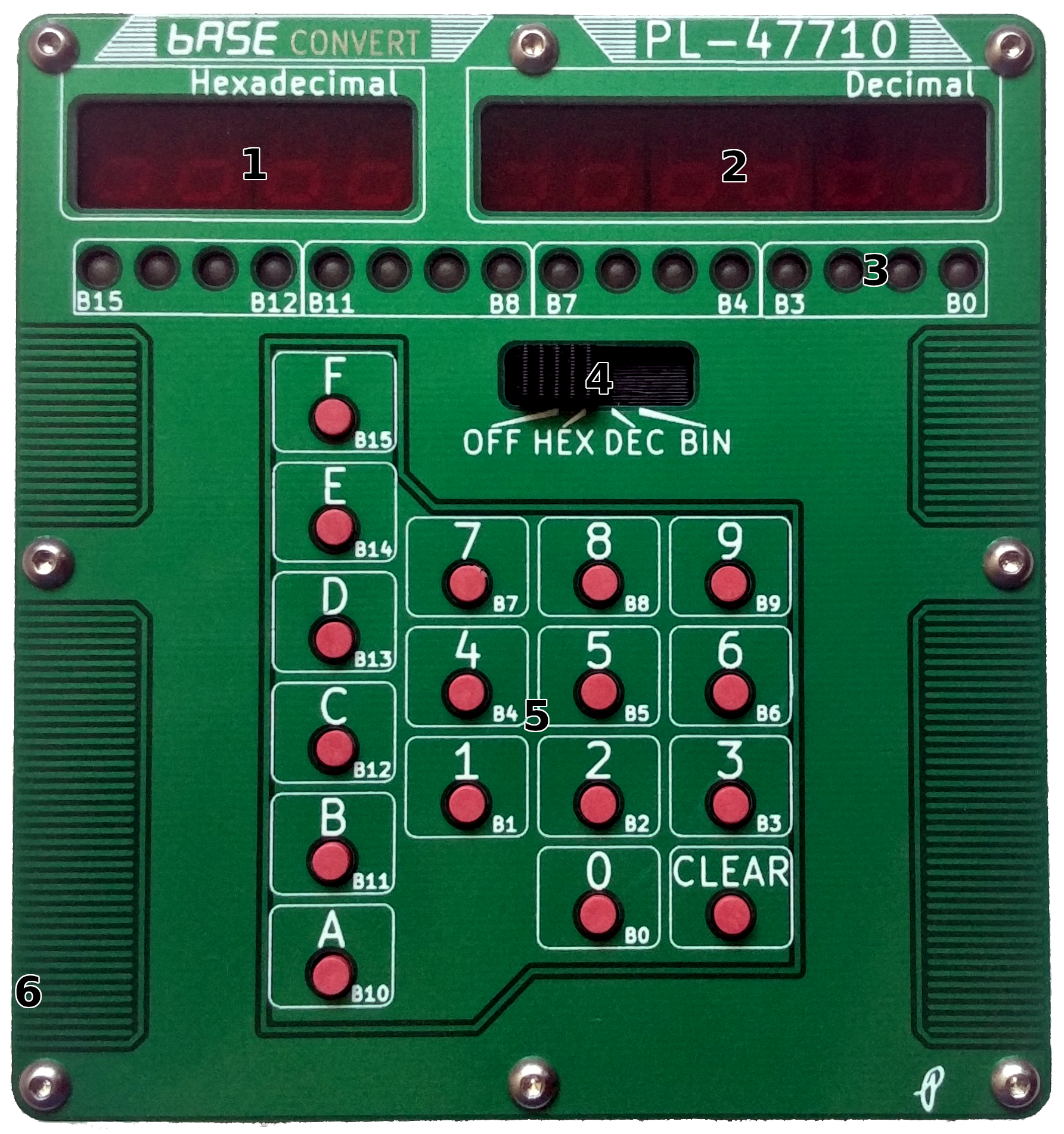
Base Convert PL-47710 Rev. A is a simple desk/handheld device to convert between hexadecimal, decimal, and binary. The unit features separate displays for each number base for easy comparison between the three bases. User input is possible using 16 alphanumeric keys and an input mode selector switch. The device is powered by 4 AA alkaline batteries with an estimated 100 hours of battery life.
| Item | Specification |
|---|---|
| Hex Display | 4 digit, 7 segment red LED |
| Decimal Display | 6 digit, 7 segment red LED |
| Binary Display | 16 red LEDs |
| User Input | 16 digit alphanumeric keypad |
| Power | 4 AA Alkaline |
| Battery Life | 100 hrs estimated |
| Width | 94mm / 3.7" |
| Height | 100mm / 3.94" |
| Thickness | 35mm / 1.38" |
| Weight, with 4xAA | 275g / 9.65oz |
Using a 1.5mm hex bit remove the eight M2.5 button head hex bolts holding the back panel to the unit. Install 4x AA batteries into the battery holder attached to the main PCB. Follow the polarity imprinted on the battery holder. The device does have reverse polarity projection that should project it from damage but it is still advisable to not reverse the polarity of the batteries. Replace the back panel after installing the batteries.
To turn on the unit slide the selector switch from the OFF position to any of the three input positions. The display will illuminate at the default value of 0.
Slide the selector switch to HEX. The right most decimal on the hexadecimal display will illuminate when the unit is in hexadecimal input mode. Use the alphanumeric keypad to input a hexadecimal number, all three displays will update after each key press. If the hexadecimal number exceeds 4 digits the left most digit will be dropped to shift in the right most digit. Clearing the display by pressing the CLEAR button will set the hexadecimal number to 0.
Slide the selector switch to DEC. The right most decimal on the decimal display will illuminate when the unit is in decimal input mode. Use the alphanumeric keypad to input a decimal number, all three displays will update after each key press. If the decimal number will exceed 65,535 with the requested key press the device will no longer shift in new decimal digits while in decimal input mode. Clearing the display will set the decimal number to 0.
Slide the selector switch to BIN. There is no indicator on any of the displays to indicate that the unit is in binary input mode. Use the alphanumeric keypad to toggle the bits of the binary number displayed on the binary display, all three displays will update after each key press. Pressing the CLEAR button will set the binary number to 0.
It is possible to update the firmware. A TI Launchpad and cable is required. The pin out of the programming header is as follows when looking at the unit from the front.
External power is required, install 4x AA batteries before updating the firmware and place the selector switch in any of the input positions.
The most current firmware is located here: https://github.com/sdp8483/base_convert/tree/master/firmware/base_convert CCS 8.x.x or newer is required to update the firmware. Please search online for help using CCS and uploading firmware since this is outside of the scope of this document.
| Qty | Value | Footprint | References |
|---|---|---|---|
| 14 | Q_PNP_BEC | TO_SOT_Packages_SMD:SOT-23 | Q2, Q3, Q4, Q5, Q10, Q11, Q12, Q13, Q14, Q15, Q16, Q17, Q18, Q19 |
| 12 | Q_NPN_BEC | TO_SOT_Packages_SMD:SOT-23 | Q6, Q7, Q8, Q9, Q20, Q21, Q22, Q23, Q24, Q25, Q26, Q27 |
| 7 | 4.7k | Resistors_SMD:R_Array_Convex_4x1206 | RN1, RN3, RN4, RN5, RN6, RN9, RN10 |
| 5 | LTD-2601WC | Lite-On:Display_Lite-On_LTD-2601WC | DS1, DS2, DS3, DS4, DS5 |
| 3 | 150 | Resistors_SMD:R_Array_Convex_4x1206 | RN2, RN7, RN8 |
| 2 | 1uF | Capacitors_SMD:C_0805 | C1, C4 |
| 1 | 0 | Switch_CK:CK_PTS645_6mm_SMD | SW9 |
| 1 | 1 | Switch_CK:CK_PTS645_6mm_SMD | SW10 |
| 1 | 100nF | Capacitors_SMD:C_0805 | C3 |
| 1 | 102k | Resistors_SMD:R_0603 | R1 |
| 1 | 10uF | Capacitors_SMD:C_0805 | C2 |
| 1 | 2 | Switch_CK:CK_PTS645_6mm_SMD | SW6 |
| 1 | 25.5k | Resistors_SMD:R_0603 | R2 |
| 1 | 3 | Switch_CK:CK_PTS645_6mm_SMD | SW2 |
| 1 | 4 | Switch_CK:CK_PTS645_6mm_SMD | SW11 |
| 1 | 4 Cell AA Battery Clip | MPD:BC4AAW | BT1 |
| 1 | 5 | Switch_CK:CK_PTS645_6mm_SMD | SW7 |
| 1 | 6 | Switch_CK:CK_PTS645_6mm_SMD | SW3 |
| 1 | 7 | Switch_CK:CK_PTS645_6mm_SMD | SW12 |
| 1 | 8 | Switch_CK:CK_PTS645_6mm_SMD | SW8 |
| 1 | 9 | Switch_CK:CK_PTS645_6mm_SMD | SW4 |
| 1 | A | Switch_CK:CK_PTS645_6mm_SMD | SW13 |
| 1 | B | Switch_CK:CK_PTS645_6mm_SMD | SW15 |
| 1 | BIT0 | LightPipe_Bivar:LED_0805_LightPipe_VLP | D13 |
| 1 | BIT1 | LightPipe_Bivar:LED_0805_LightPipe_VLP | D9 |
| 1 | BIT10 | LightPipe_Bivar:LED_0805_LightPipe_VLP | D7 |
| 1 | BIT11 | LightPipe_Bivar:LED_0805_LightPipe_VLP | D3 |
| 1 | BIT12 | LightPipe_Bivar:LED_0805_LightPipe_VLP | D16 |
| 1 | BIT13 | LightPipe_Bivar:LED_0805_LightPipe_VLP | D12 |
| 1 | BIT14 | LightPipe_Bivar:LED_0805_LightPipe_VLP | D8 |
| 1 | BIT15 | LightPipe_Bivar:LED_0805_LightPipe_VLP | D4 |
| 1 | BIT2 | LightPipe_Bivar:LED_0805_LightPipe_VLP | D5 |
| 1 | BIT3 | LightPipe_Bivar:LED_0805_LightPipe_VLP | D1 |
| 1 | BIT4 | LightPipe_Bivar:LED_0805_LightPipe_VLP | D14 |
| 1 | BIT5 | LightPipe_Bivar:LED_0805_LightPipe_VLP | D10 |
| 1 | BIT6 | LightPipe_Bivar:LED_0805_LightPipe_VLP | D6 |
| 1 | BIT7 | LightPipe_Bivar:LED_0805_LightPipe_VLP | D2 |
| 1 | BIT8 | LightPipe_Bivar:LED_0805_LightPipe_VLP | D15 |
| 1 | BIT9 | LightPipe_Bivar:LED_0805_LightPipe_VLP | D11 |
| 1 | C | Switch_CK:CK_PTS645_6mm_SMD | SW16 |
| 1 | CLEAR | Switch_CK:CK_PTS645_6mm_SMD | SW14 |
| 1 | D | Switch_CK:CK_PTS645_6mm_SMD | SW17 |
| 1 | E | Switch_CK:CK_PTS645_6mm_SMD | SW18 |
| 1 | F | Switch_CK:CK_PTS645_6mm_SMD | SW5 |
| 1 | ISP | Pin_Headers:Pin_Header_Straight_1x04_Pitch2.54mm | J1 |
| 1 | LOGO | Artwork:sn_label | G*** |
| 1 | LOGO | PL_logo:logo_height_10mm | G*** |
| 1 | MIC5317-3.3YM5-TR | TO_SOT_Packages_SMD:SOT-23-5 | U1 |
| 1 | MSP430FR2033IPMR | Housings_QFP:LQFP-64_10x10mm_Pitch0.5mm | U2 |
| 1 | Q_PMOS_GSD | TO_SOT_Packages_SMD:SOT-23 | Q1 |
| 1 | SELECT | Switch_CK:DP4T_SS-24E06-TG5P | SW1 |
| 1 | VTARG_EN | Resistors_SMD:R_1206 | JP1 |
| 1 | Vin | Connectors_JST:JST_PH_S2B-PH-K_02x2.00mm_Angled | J3 |
The 90 most common of 98 parts.
It measures 93.3 × 100 mm and has 2 copper layers, 1.6 mm thick.
98 parts, built around the MSP430FR2033IPMR, MIC5317-3.3YM5-TR, LTD-2601WC and BIT3. The full list of its parts is on this page, with links to each part's symbol and footprint where PCBKit's library has them.
From the sdp8483/base_convert repository on GitHub, at the commit this page was made from: the board is main_pcb/base_convert.kicad_pcb. PCBKit opens the board in the browser, with nothing to install.
Its repository publishes it under the MIT licence: you may reuse it on that licence's terms (keep the author's notice, and for a copyleft licence share your changes alike).


DragonMinded/minidragon
Hardware and software files for the MiniDragon CPU.

himanshu40304/PCB_automation
This repository contains the automation workflow and some projects made by using this workflow which makes pcb designs using ai assistance faster than making pcb designs manually.

OpenSiPM/sipm-bias-control
Single channel silicon photomultipliers for high-speed fluorescence imaging

BelaPlatform/gliss-hardware
You can find the source KiCad files for the Gliss module in this repository. This project is open hardware and under the Creative Commons Share Alike license 4.0.


DRCDanilo/CommTrainer_PCB
PCB with STM32G431KBT6 microcontroller and ADXL343 accelerometer, to work with USB, SPI, I2C and UART communication protocols.