2 layers61.7 × 46.7 mm

 sdeleers/esloq
Esloq is a startup I worked on from 2014 to 2016. All code written by Kenny Kuchera and me.
Slock is an open-source printed circuit board by sdeleers, from the sdeleers/esloq repository on GitHub. It is a 2-layer board of 40 × 52 mm with 52 parts on 35 nets, routed with 520 tracks and 25 vias.
It is built around the ATMEGA328P-AU and BLE112-A-V1. Its parts include 19 capacitors, 14 resistors, 5 ICs, 4 connectors and 2 switches. It belongs with the AVR (ATmega, ATtiny) boards of this library.


Project date: 2014-2016
Esloq is a startup I worked on from 2014 to 2016. All code written by Kenny Kuchera and me.
Esloq is a door lock that can be opened with a smartphone via Bluetooth. It consists of a wooden box that is mounted on the door lock cylinder. The wooden box contains the printed circuit board and a motor that actuates the lock.
A demo video of the esloq:
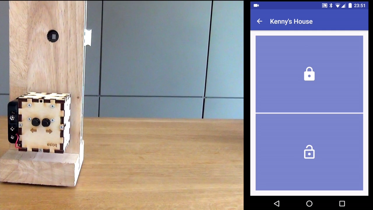
Esloq uses authentication and encryption to ensure that only the people you invite can enter. Whenever you want to open a door with your phone, the phone requests a ticket from the esloq webserver. The server returns the ticket that is authenticated encrypted under a symmetric key that is shared between the door lock and the esloq webserver (the phone does not have this key). The phone then forwards this ticket to the lock which verifies its authenticity and opens the door if it's valid.
This repository contains:
The printed circuit board:
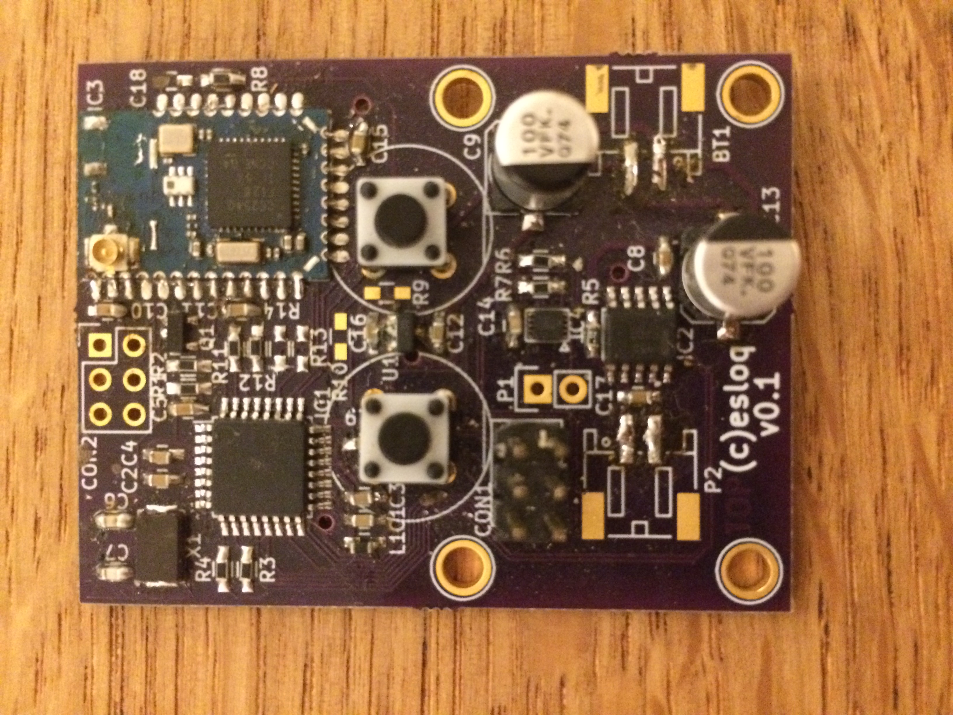
| Qty | Value | Footprint | References |
|---|---|---|---|
| 10 | 10k | Resistors_SMD:R_0603_HandSoldering | R1, R2, R3, R4, R7, R8, R11, R12, R13, R14 |
| 9 | 0.1u | Capacitors_SMD:C_0603_HandSoldering | C1, C2, C3, C4, C5, C14, C17, C18, C19 |
| 6 | 1u | Capacitors_SMD:C_0603_HandSoldering | C8, C10, C11, C12, C15, C16 |
| 2 | 100u | Capacitors_SMD:c_elec_6.3x5.8 | C9, C13 |
| 2 | 22p | Capacitors_SMD:C_0603_HandSoldering | C6, C7 |
| 2 | SW_PUSH | Buttons_Switches_ThroughHole:Push_E-Switch_KS01Q01 | SW1, SW2 |
| 1 | 0.1 | Resistors_SMD:R_0603_HandSoldering | R5 |
| 1 | 0.5M | Resistors_SMD:R_0603_HandSoldering | R10 |
| 1 | 1.5M | Resistors_SMD:R_0603_HandSoldering | R9 |
| 1 | 10u | Capacitors_SMD:C_0603_HandSoldering | L1 |
| 1 | 3k | Resistors_SMD:R_0603_HandSoldering | R6 |
| 1 | 6PIN_CC | Pin_Headers:Pin_Header_Straight_2x03 | CON2 |
| 1 | 8M | Crystals:Crystal_AMB3 | X1 |
| 1 | ATMEGA328P-A | Housings_QFP:TQFP-32_7x7mm_Pitch0.8mm | IC1 |
| 1 | AVR-ISP-6 | Pin_Headers:Pin_Header_Straight_2x03 | CON1 |
| 1 | BC849 | TO_SOT_Packages_SMD:SOT-23 | Q1 |
| 1 | BLE112 | My_Modules:BLE112 | IC3 |
| 1 | Battery | Connectors_JST_PH:Connectors_JST_S2B-PH-SM4-TB | BT1 |
| 1 | CONN_01X02 | Pin_Headers:Pin_Header_Straight_1x02 | P1 |
| 1 | H_BRIDGE | My_Modules:SOIC-10 | IC2 |
| 1 | INA300 | My_Modules:PWSON10 | IC4 |
| 1 | MCP1700T | TO_SOT_Packages_SMD:SOT-23 | U1 |
| 1 | MOTOR_PINS | Connectors_JST_PH:Connectors_JST_S2B-PH-SM4-TB | P2 |
The 48 most common of 52 parts.


dmcke5/NucDeck
The Open Source DIY Handheld Gaming PC!


profdc9/RFBitBanger
A QRP digital transceiver created from readily available parts for off-the-grid maintenance

futureshocked/KLP4e_MCU-Datalogger
This is the repository for the "MCU Datalogger" project.


sportiduino/sportiduino
Electronic timing system for orienteering and similar outdoor sports events on Arduino
It measures 40 × 52 mm and has 2 copper layers, 1.6 mm thick.
52 parts, built around the ATMEGA328P-AU and BLE112-A-V1. The full list of its parts is on this page, with links to each part's symbol and footprint where PCBKit's library has them.
From the sdeleers/esloq repository on GitHub, at the commit this page was made from: the board is pcb/slock.kicad_pcb. PCBKit opens the board in the browser, with nothing to install.
Its repository states no licence, so its author keeps all rights: ask sdeleers before reusing the design.