

2 layers101.5 × 83 mm

 screwbreaker/OpenA1200RTC27
Open Hardware RTC module for the Amiga 1200.
OpenA1200RTC is an open-source printed circuit board by screwbreaker, from the screwbreaker/OpenA1200RTC repository on GitHub. It is a 2-layer board of 44.5 × 35.8 mm with 14 parts on 48 nets, routed with 140 tracks and 15 vias.
It is built around the MSM6242BGSK and BAT54C. Its parts include 5 resistors, 2 capacitors, 1 IC, 1 diode and 1 connector. It belongs with the retro computing and games boards of this library.
OpenA1200RTC is an Open Hardware RTC module for the Amiga 1200.
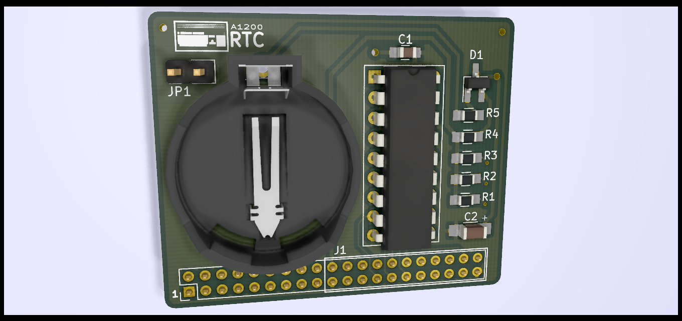
This RTC circuit is actually used on other free projects like: The mini A501 for Amiga 500, The OpenAmiga600RamExpansion for Amiga 600.
The main goal was to made an RTC module using the same components, same clock IC, same battery holder, etc. In this way with pratically the same BOM is possible to have the RTC for most of the Amiga computers family, A500, A600 ad now also the A1200.
The entire RTC circuit has been designed for an Epson RTC62421 or RTC72421, which don't need an external crystal nor any calibration. Both can be bought very cheaply from China; they will most likely be second-hand "pulls", but usually they will work fine.
The other components have some degree of flexibility:
Note that if you plan to store your Amiga or not to use it in a while, you are recommended to remove the battery. Failing to do this killed many A500+ computers and many A501 expansions in the past. The CR2032 battery used in this project is probably safer than the batteries used in those devices, but still I would not leave one in an unused Amiga. You have been warned.
Open the A1200, locate the P9B connector, it is between the Kickstart ROMs and the RAM ICs. The PB9 is a 40 pin connector, but in most A1200 only the 22 on the right are populated. And they are the only pins needed to allow the RTC to work. On this board a full 40 pin connector is used, mostly because it seem easier to find, and because help to avoid mistakes in the installation.
Align the pin 1 of the board with the pin 1 of the PB9 connector and gently push it down, an extra silkscreen on the PCB help to identify and align the 22 usable pins.
This board is not designed specifically to fit with the shield, but, nevertheless it seem to fit even with it. Except for the little RTC cover of the shield, that must be removed. The board was made specifically for reuse the same components of other expansions, so the shape was made according to the size of the components, not for be an optimal fit into any A1200. There could be space problems with other expansion. In this case I suggest to look for other RTC modules specifically made to be smaller.
If an accelerator board with the RTC module is installed, don't use this board, or disable one of the two RTC. To disable this board open the jumper JP1.
There are also some expansions that use the clock port for other things than the RTC, I have no clue if this board will work with them, or even if it can fit on them.
OpenA1200RTC is Open Hardware. If you make any modifications to the board, please contribute them back.
OpenA1200RTC is provided to you 'as is' and without any express or implied warranties whatsoever with respect to its functionality, operability or use, including, without limitation, any implied warranties of merchantability, fitness for a particular purpose or infringement. We expressly disclaim any liability whatsoever for any direct, indirect, consequential, incidental or special damages, including, without limitation, lost revenues, lost profits, losses resulting from business interruption or loss of data, regardless of the form of action or legal theory under which the liability may be asserted, even if advised of the possibility or likelihood of such damages.
Since the project is open you are free to get the PCBs made by your preferred manufacturer, however in case you want to support the development, you can order them from PCBWay:

You get cheap, professionally-made and good quality PCBs, that will help with this and other projects. You won't even have to worry about the various PCB options, it's all pre-configured for you!
Also, if you still have to register to that site, you can use this link to get some bonus initial credit (and some more to help the author of projects like this).
Again, if you want to use another manufacturer, feel free to, don't feel obligated :).
| Qty | Value | Footprint | References |
|---|---|---|---|
| 3 | 10k | Resistors_SMD:R_0805_HandSoldering | R1, R2, R3 |
| 2 | 220 | Resistors_SMD:R_0805_HandSoldering | R4, R5 |
| 1 | 100n | Capacitors_SMD:C_0805_HandSoldering | C1 |
| 1 | 2.2uF | Capacitors_SMD:C_1206_HandSoldering | C2 |
| 1 | A1200 | library:A1200 | V2 |
| 1 | BAT54C | TO_SOT_Packages_SMD:SOT-23_Handsoldering | D1 |
| 1 | Battery_Holder | library:Battery_Holder_Coin_2032_BS-7 | BT1 |
| 1 | Connector_2x20_2mm | Pin_Headers:Pin_Header_Straight_2x20_Pitch2.00mm | J1 |
| 1 | Jumper | Pin_Headers:Pin_Header_Straight_1x02_Pitch2.54mm | JP1 |
| 1 | MSM6242B | Housings_DIP:DIP-18_W7.62mm_Socket | U1 |
| 1 | OSHW | library:OSHW | V1 |


theta-machines/DEV-G2-NANO
The G2 Nano is powered by a record-breaking 1 GHz Arm Cortex-M7 processor, combining the performance of an application processor with real-time determinism.

Duet3D/Duet-2-Hardware
The KiCAD source for the Duet 3d printer controller see www.duet3d.com


jkramarz/TheTick
The Tick is the next evolution in covert access control system implants for simulating adversary-in-the-middle attacks.

M17-Project/Module_17
M17 modem board for 9600-baud capable radios

It measures 44.5 × 35.8 mm and has 2 copper layers, 1.6 mm thick.
14 parts, built around the MSM6242BGSK and BAT54C. The full list of its parts is on this page, with links to each part's symbol and footprint where PCBKit's library has them.
From the screwbreaker/OpenA1200RTC repository on GitHub, at the commit this page was made from: the board is OpenA1200RTC.kicad_pcb. PCBKit opens the board in the browser, with nothing to install.
Its repository states no licence, so its author keeps all rights: ask screwbreaker before reusing the design.