2 layers65 × 36.3 mm

 scottalmond/Pendant
The purpose of this project is to develop a piece of artisan eletronics to serve as a prize for an eletronics competition. The design consists of a PCB and 3D-printed case.
Pendant pcb is an open-source printed circuit board by scottalmond, from the scottalmond/Pendant repository on GitHub. It is a 2-layer board of 50.8 × 67.3 mm with 35 parts on 35 nets, routed with 369 tracks and 21 vias.
It is built around the TPA6211A1DGNR, SK6812 and S2B-PH-SM4-TB(LF)(SN), with the 10118193-0001LF, JS102011SAQN and M20-7810445 among its other parts. Its parts include 11 diodes, 9 capacitors, 6 ICs, 4 connectors and 3 resistors. It belongs with the AVR (ATmega, ATtiny) boards of this library.


The purpose of this project is to develop a piece of artisan eletronics to serve as a prize for an eletronics competition. The design consists of a PCB and 3D-printed case. The CAD model for the case has been excluded from this project because it incorporates proprietary elements.
Development Tools Arduino IDE KiCAD FreeCAD
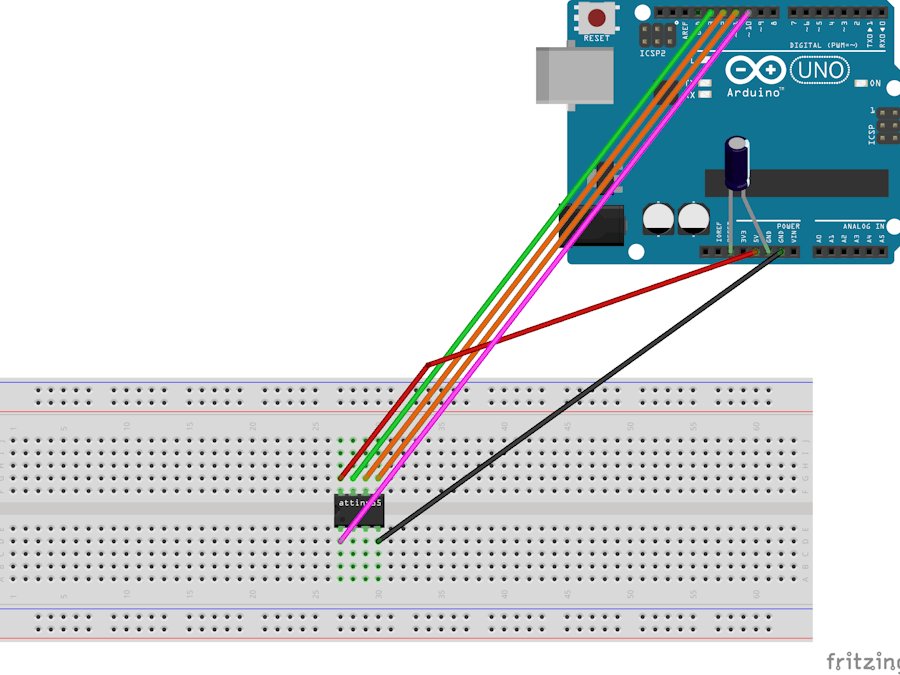
The J3 header has a 1:1 pinout matching the Attiny85 processor. Instructions for programming the Attiny85 using an Arduino is documented at the start of the Arduino code. Once the Arduino has been programmed with the ArduinoAsISP program, it can be connected to the J3 programming header using the following connections: https://hackster.imgix.net/uploads/cover_image/file/50546/Programming%20ATtiny85%20with%20Arduino%20Uno_bb.png?auto=compress%2Cformat&w=900&h=675&fit=min
License CC BY 4.0: Scott Almond https://creativecommons.org/licenses/by/4.0/
| Qty | Value | Footprint | References |
|---|---|---|---|
| 11 | SK6812 | Misc:LED_SK6812_PLCC4_5.0x5.0mm_P3.2mm | D1, D2, D3, D4, D5, D6, D7, D8, D9, D10, D11 |
| 3 | Debug | Misc:Debug_2p | U1, U2, U5 |
| 2 | 100nF | Capacitors_SMD:C_0805 | C8, C9 |
| 2 | 1uF | Capacitors_SMD:C_0805 | C1, C4 |
| 2 | 27k | Resistors_SMD:R_0805 | R2, R3 |
| 2 | 4.7nF | Capacitors_SMD:C_0805 | C5, C6 |
| 2 | 4.7uF | Capacitors_SMD:C_0805 | C2, C3 |
| 2 | S2B-PH-SM4-TB(LF)(SN) | S2B-PH-SM4-TB_LF__SN_:JST_S2B-PH-SM4-TB(LF)(SN) | J2, J4 |
| 1 | 10118193-0001LF | Misc:FCI_10118193-0001LF | J1 |
| 1 | 3.9k | Resistors_SMD:R_0805 | R1 |
| 1 | 47uF | Capacitors_SMD:C_0805 | C7 |
| 1 | ATTINY85-S | attiny:ATTINY85-20SU | IC1 |
| 1 | EVQ-P7C01P | SamacSys_Parts:EVQP7C01P | S1 |
| 1 | JS102011SAQN | JS102011SAQN:SW_JS102011SAQN | S2 |
| 1 | M20-7810445 | M20-7810445:M207810445 | J3 |
| 1 | MCP73832T-2ACI/OT | mcp:MCP73831T-2ACI&slash_OT | U3 |
| 1 | TPA6211A1DGNR | tpa:TPA6211A1DGNR | U4 |


n416/katanori
⚠ 2026-09-15 に全体を書き直した(2026-08-19 の状態のまま止まっていて、「筐体 v2 を設計中」「電池はまだ」と書いてあった)。

MeesCode/gameboy-pcb
custom gameboy-esque pcb running an stm32 and my own tiny game engine


ShawnHymel/rpi-pico-debugger-shoe
Stackable debugger board for the Raspberry Pi Pico. Solder long headers to this debugger board in order to connect the Pico to it.
It measures 50.8 × 67.3 mm and has 2 copper layers, 1.6 mm thick.
35 parts, built around the TPA6211A1DGNR, SK6812, S2B-PH-SM4-TB(LF)(SN) and 10118193-0001LF. The full list of its parts is on this page, with links to each part's symbol and footprint where PCBKit's library has them.
From the scottalmond/Pendant repository on GitHub, at the commit this page was made from: the board is src/pcb/pendant_pcb.kicad_pcb. PCBKit opens the board in the browser, with nothing to install.
Its repository states no licence, so its author keeps all rights: ask scottalmond before reusing the design.