2 layers128.6 × 76.7 mm
ESP Edgedevice
sarinsanyal/pcb-shems
This Smart Edge Node is an industrial/home energy monitoring and switching board that bridges high-voltage AC mains power with low-voltage microcontroller logic.
22 parts

 sarinsanyal/pcb-shems
This Smart Edge Node is an industrial/home energy monitoring and switching board that bridges high-voltage AC mains power with low-voltage microcontroller logic.
ESP Edgedevice is an open-source printed circuit board by sarinsanyal, from the sarinsanyal/pcb-shems repository on GitHub. It is a 2-layer board of 125 × 100 mm with 68 parts on 50 nets.
It is built around the HLK-5M05, AMC1200SDUBR and MCP3202-CI/P, with the AMS1117-5.0, PC817X3NSZ1B and HB9500-9.5-3P among its other parts. Its parts include 20 capacitors, 19 resistors, 10 ICs, 5 diodes and 4 connectors. It belongs with the ESP32 and RISC-V boards of this library.


A robust, mixed-signal hardware platform designed for AC mains energy monitoring, power conversion, and isolated load control. Engineered with high-voltage clearance, discrete signal shifting, and inductive load protection.
This Smart Edge Node is an industrial/home energy monitoring and switching board that bridges high-voltage AC mains power with low-voltage microcontroller logic. Designed with a focus on analog hardware reliability, power distribution, and galvanic isolation, the design integrates on-board AC-DC regulated conversion, discrete MOSFET level translation, and an optoisolated transistor relay driver with flyback suppression.
The system utilizes an ESP8266 (Lolin) for edge processing and software-driven UART communication with a PZEM-004T metering module, enabling real-time telemetry publication over Wi-Fi (MQTT/HTTP) while safely controlling heavy AC electrical loads.
| 3D PCB Render | PCB Layout & Routing | Hardware Schematic |
|---|---|---|
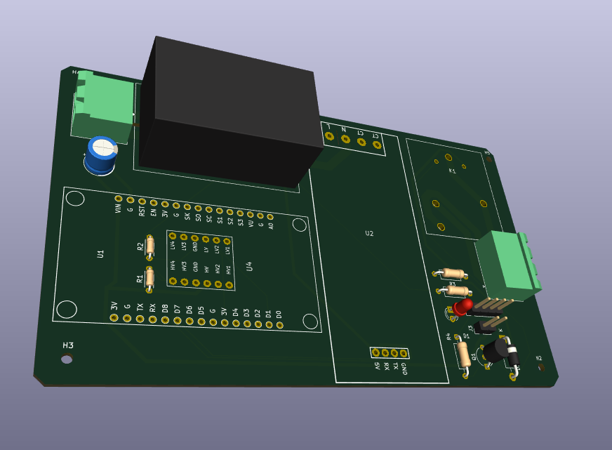 | 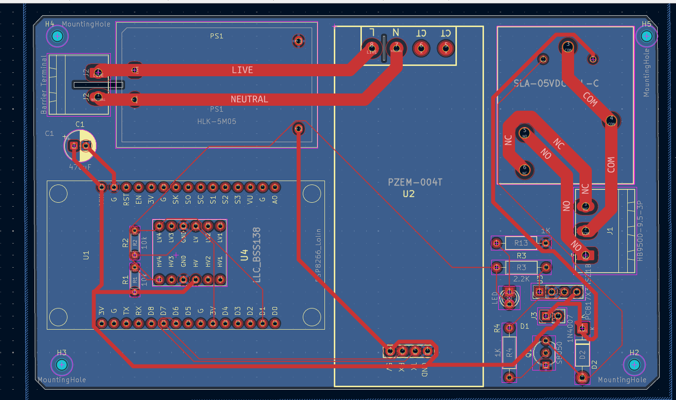 | 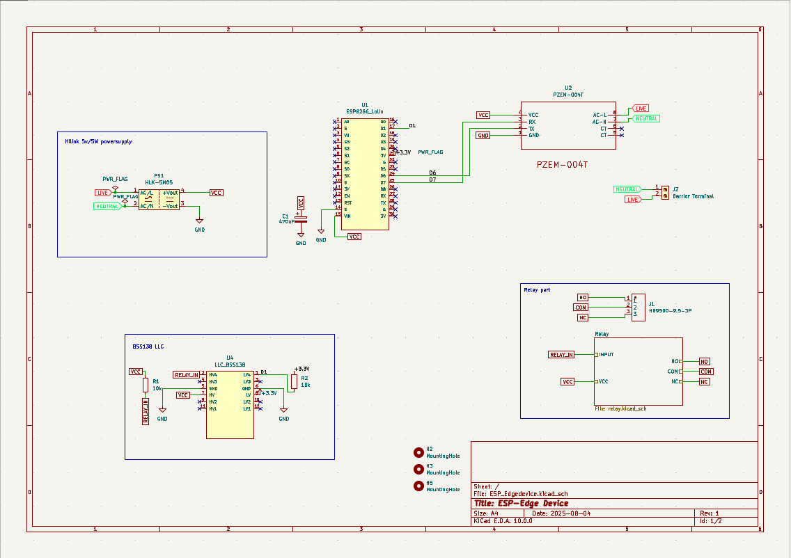 |
| KiCad 3D Ray-traced Board View | 2-Layer Trace & High-Voltage Clearance | System Schematic Architecture |
| Subsystem | Circuitry / Components | Function |
|---|---|---|
| Power Supply | HLK-5M05 + $470\ \mu\text{F}$ Capacitor | AC-DC Step-down ($230\text{V AC} \to 5\text{V DC}$) & Rail Filtering |
| Microcontroller | ESP8266 (Lolin V3 Footprint) | Wireless Telemetry, MQTT, SoftSerial UART, GPIO Control |
| Logic Level Conversion | BSS138 MOSFET Level Shifter ($U4$) | $3.3\text{V} \leftrightarrow 5\text{V}$ Logic Level Translation |
| Relay Driver | PC817 Optocoupler + S8050 NPN + 1N4007 Diode | Isolated coil energization & Back-EMF suppression |
| AC Load Control | SLA-05VDC High-Power Relay | Heavy AC Load ON/OFF Disconnect |
| Energy Measurement | PZEM-004T AC Sensor | High-accuracy RMS Voltage, Current, & Power Telemetry |
Suvam Seth Power Engineering Student | PCB Design | Analog Electronics & Systems Design
Sarin Sanyal Power Engineering Student | Analog & Mixed-Signal Circuit Design | Embedded Hardware | AI
| Qty | Value | Footprint | References |
|---|---|---|---|
| 12 | 100nF | Capacitor_SMD:C_1206_3216Metric | C9, C9, C10, C10, C11, C11, C12, C13, C13, C14, C15, C16 |
| 4 | 1k | Resistor_SMD:R_1206_3216Metric | R2, R12, R15, R18 |
| 4 | MountingHole | MountingHole:MountingHole_2.1mm | H1, H2, H3, H4 |
| 3 | 10k | Resistor_SMD:R_1206_3216Metric | R13, R14, R16 |
| 3 | 1K | Resistor_SMD:R_1206_3216Metric | R1, R3, R11 |
| 3 | OPA333xxDBV | Package_TO_SOT_SMD:SOT-23-5 | U5, U6, U6 |
| 2 | 100K | Resistor_SMD:R_1206_3216Metric | R8, R9 |
| 2 | 10uF | Capacitor_THT:CP_Radial_D5.0mm_P2.50mm | C6, C7 |
| 2 | 1M | Resistor_THT:R_Axial_DIN0207_L6.3mm_D2.5mm_P10.16mm_Horizontal | R6, R7 |
| 2 | 1N4007 | Diode_THT:D_DO-41_SOD81_P10.16mm_Horizontal | D2, D4 |
| 2 | AMC1200SDUBR | AMC1200SDUBR:DUB0008A-IPC_A | U4, U8 |
| 2 | MCP3202 | Package_SO:TSSOP-8_4.4x3mm_P0.65mm | U7, U7 |
| 1 | 0.1uF | Capacitor_SMD:C_1206_3216Metric | C8 |
| 1 | 0.33 Ω, 1206 | Resistor_SMD:R_1206_3216Metric | R12 |
| 1 | 100R | Resistor_THT:R_Axial_DIN0309_L9.0mm_D3.2mm_P12.70mm_Horizontal | R17 |
| 1 | 100nF X2, 275 V AC | Capacitor_THT:C_Rect_L18.0mm_W5.0mm_P15.00mm_FKS3_FKP3 | C17 |
| 1 | 10uF | Capacitor_SMD:C_1206_3216Metric | C5 |
| 1 | 1A,250V AC | Fuse:Fuseholder_Cylinder-5x20mm_Schurter_0031_8201_Horizontal_Open | F1 |
| 1 | 220K | Resistor_SMD:R_1206_3216Metric | R10 |
| 1 | 220R 1W | Resistor_THT:R_Axial_DIN0414_L11.9mm_D4.5mm_P15.24mm_Horizontal | R4 |
| 1 | 25A Slow-Blow | Fuse:Fuseholder_Cylinder-6.3x32mm_Schurter_0031-8002_Horizontal_Open | F2 |
| 1 | 470k | Resistor_THT:R_Axial_DIN0207_L6.3mm_D2.5mm_P10.16mm_Horizontal | R5 |
| 1 | 470nF X2 | Capacitor_THT:C_Rect_L26.5mm_W8.5mm_P22.50mm_MKS4 | C3 |
| 1 | 470uF | Capacitor_THT:CP_Radial_D6.3mm_P2.50mm | C1 |
| 1 | 470uF | Capacitor_THT:CP_Radial_D10.0mm_P5.00mm | C4 |
| 1 | 7.5 | Diode_SMD:D_MiniMELF | D3 |
| 1 | AMS1117-5.0 | Package_TO_SOT_SMD:SOT-223-3_TabPin2 | U3 |
| 1 | Barrier Terminal | Connector_Phoenix_MSTB:PhoenixContact_MSTBA_2,5_2-G_1x02_P5.00mm_Horizontal | J1 |
| 1 | Conn_01x02 | Connector_PinHeader_2.54mm:PinHeader_1x02_P2.54mm_Vertical | J4 |
| 1 | Conn_01x02_Pin | Connector_PinHeader_2.54mm:PinHeader_1x02_P2.54mm_Vertical | J3 |
| 1 | D_TVS | Diode_SMD:Nexperia_DSN0603-2_0.6x0.3mm_P0.4mm | D5 |
| 1 | HB9500-9.5-3P | myparts:HB9500_9.5-3P | J2 |
| 1 | HLK-5M05 | Converter_ACDC:Converter_ACDC_Hi-Link_HLK-5Mxx | PS1 |
| 1 | LED | LED_THT:LED_D3.0mm | D1 |
| 1 | PC817X3NSZ1B | Package_DIP:DIP-4_W7.62mm | U2 |
| 1 | S8050 | Package_TO_SOT_THT:TO-92_Inline_Wide | Q1 |
| 1 | SLA-05VDC-SL-C | SLA-05VDC-SL-C:RELAY-TH_SLA-XXVDC-XX-C | K1 |
| 1 | Varistor | Varistor:RV_Disc_D12mm_W4.2mm_P7.5mm | RV1 |
| 1 | XIAO ESP32C3 | myparts:XIAO_Socket_W15.24 | U1 |
sarinsanyal/pcb-shems
This Smart Edge Node is an industrial/home energy monitoring and switching board that bridges high-voltage AC mains power with low-voltage microcontroller logic.

mikenorgate/3d-printer-power-hat
A Raspberry PI HAT for controlling power to your 3D printer

btanqy/LLC-GaN-Protoboard
This board will be a prototype GaN based LLC converter, with a target rating of 80W with 24V input to 400V output, ideally for renewable power conversion and high voltage applications in plasma generation.

svpetry/TeslaBMBCheck
Simple device that reads the voltage levels and temperatures from a Tesla Model S BMB board.

svpetry/12VSupport
System to support a vehicle 12V electrical system with a LiIon battery to prevent the lead battery from depletion.

Sakib-Ansari/Linear_Programmable_Power_Supply
This repository contains the complete KiCad project for a multi-board linear programmable bench power supply. The design is organized into separate PCBs, including the Power Board, Control Board, Front Panel, Output…


It measures 125 × 100 mm and has 2 copper layers, 1.6 mm thick.
68 parts, built around the HLK-5M05, AMC1200SDUBR, MCP3202-CI/P and AMS1117-5.0. The full list of its parts is on this page, with links to each part's symbol and footprint where PCBKit's library has them.
From the sarinsanyal/pcb-shems repository on GitHub, at the commit this page was made from: the board is PCB_SHEMS/ESP_Edgedevice/ESP_Edgedevice.kicad_pcb and its schematic PCB_SHEMS/ESP_Edgedevice/ESP_Edgedevice.kicad_sch. PCBKit opens the board in the browser, with nothing to install.
Its repository states no licence, so its author keeps all rights: ask sarinsanyal before reusing the design.