2 layers37.3 × 75 mm
ECE445L Lab7
samienr/ECE445L-final
Public copy of our Embedded Systems Design Lab final project
31 parts

 samienr/ECE445L-final
Public copy of our Embedded Systems Design Lab final project
ECE445L Starter is an open-source printed circuit board by samienr, from the samienr/ECE445L-final repository on GitHub. It is a 2-layer board of 126 × 97.2 mm with 39 parts on 83 nets, routed with 420 tracks and 13 vias.
It is built around the EK-TM4C123GXL, ESP8266-12E and IRLD024PBF. Its parts include 12 capacitors, 11 resistors, 4 ICs, 2 connectors and 1 diode. It belongs with the ESP8266 boards of this library.

This is a public forked copy of my team's Embedded Systems Design Lab final project: Motion Controlled Street Fighter, a game inspired by the Nintendo Wii's wireless motion controllers.
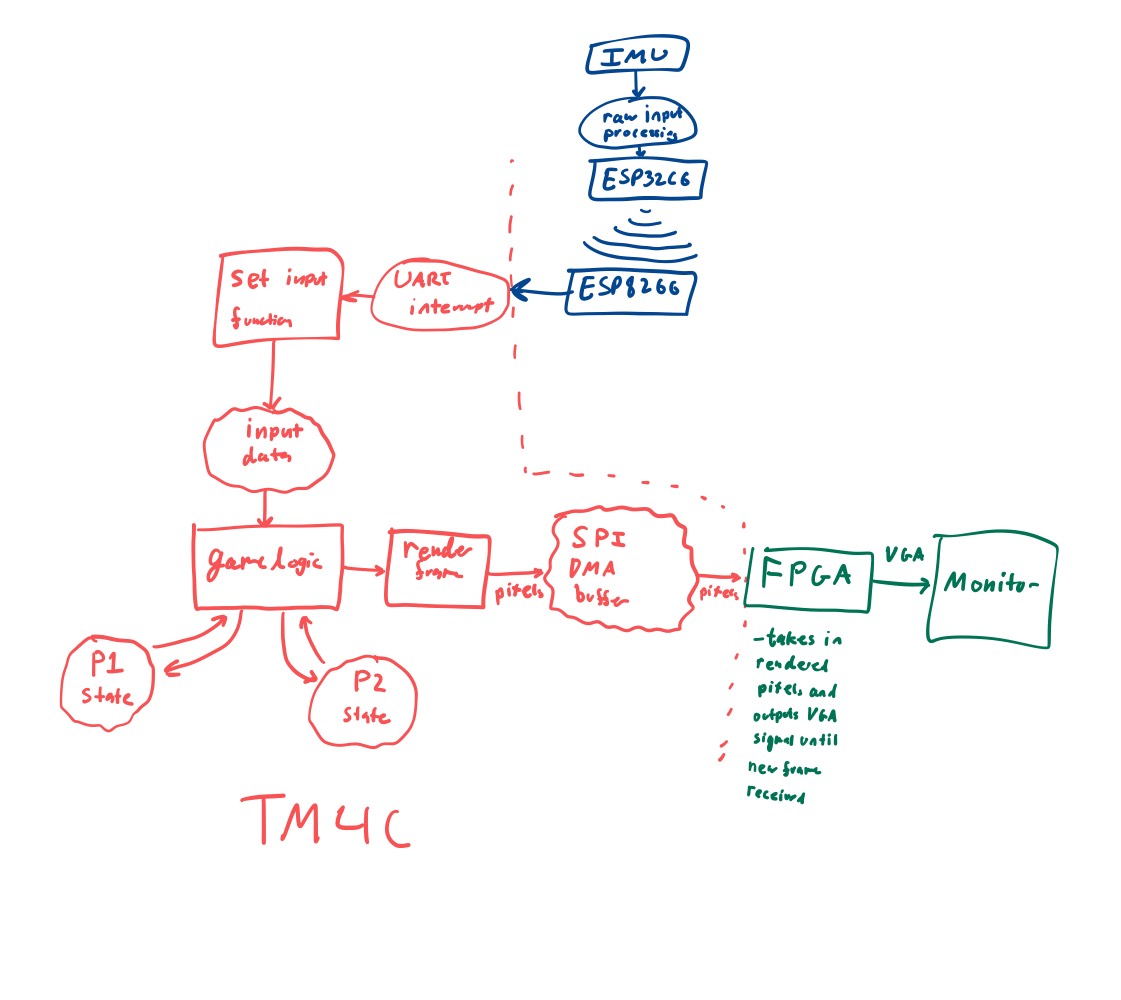
This game was designed to run on a TI tm4c123gh6pm microcontroller paired with a Xilinx Basys3 Artix 7 FPGA board. For the controllers, we used Seeedstudio Xiao ESP32C6 microcontrollers with MPU-6050 IMU ICs. Below is a brief description of the project taken from our lab report:
We designed a Wii – like console able to receive motion data from two wireless remotes, process game logic for a light version of Streetfighter that we designed, and then output audio to a speaker, and output 320x240 resolution to a VGA monitor at 30 frames per second using an FPGA as an intermediate frame buffer between the TM4C and VGA monitor. Through this project we practiced programming multiple types of microcontrollers (ESP32, ESP8266, TM4C), interfacing with an FPGA, sensing motion from IMUs, wirelessly communicating using ESP-NOW, and designing efficient graphics pipeline under the memory and compute constraints of the TM4C by leveraging direct memory access.
Below is a simplified data flow graph of how our project is structured:

The typical explanation for the repo structure. Lab specific instructions can be found further below.
The hw folder should contain your schematic and board files for your PCB or
circuits. In labs 1-5 and 10, you will be creating schematics for your circuit
in KiCad.
The sw folder should contain your application firmware and software written
for the lab. The sw/inc folder contains firmware drivers written for you by
Professor Valvano. Feel free to write your own (in fact, in some labs, you may
be required to write your own).
You can place any other source files in the sw folder. TAs will look at the
files you create and/or modify for software quality and for running your
project.
A couple files are provided in the Resources folder so you don't have to keep searching for that one TI document. Some of them are immediately useful, like the TM4C datasheet. Others may be useful for your final project, like the TM4C_System_Design_Guidelines page.
We will extensively use Git and Github for managing lab projects. This makes it easier for TAs to grade and help debug the project by allowing us to see commit histories, maintain a common project structure, and likewise, it makes it easier for students to collaborate with partners, merge different codebases, and to debug their work by having a history of commits.
Two common ways of using Git and Github are Github Desktop and the command line. Tutorials are also abundant on the net for you to peruse. We've provided a cheatsheet for git in the Resources folder.
It is highly recommended to make the most out of Git, even if you've never used it before. Version control will save you a lot of suffering, and tools like Git or SVN are ubiquitous in the industry.
A gitignore file is added to the root of this repo that may prevent specific files from being tagged to the repo. This are typically autogenerated output files we don't care about, but sometimes other stuff (like .lib files) falls through that we want. Feel free to modify if necessary.
| Qty | Value | Footprint | References |
|---|---|---|---|
| 6 | 100nF | ECE445L:C_Axial_200mil | C1, C3, C5, C7, C10, C101 |
| 6 | 4.7uF | ECE445L:CP_Radial_Tantal200mil | C2, C4, C6, C8, C9, C103 |
| 5 | 1.5k | ECE445L:R_Axial_DIN0204_L3.6mm_D1.6mm_P7.62mm_Horizontal | R3, R4, R5, R6, R7 |
| 4 | ~ | ECE445L:MountingHole_4_40 | H1, H2, H3, H4 |
| 3 | 10k | ECE445L:R_Axial_DIN0204_L3.6mm_D1.6mm_P7.62mm_Horizontal | R1, R2, R101 |
| 3 | 12k | ECE445L:R_Axial_DIN0204_L3.6mm_D1.6mm_P7.62mm_Horizontal | R8, R9, R10 |
| 2 | Conn_02x06_Odd_Even | Connector_PinHeader_2.54mm:PinHeader_2x06_P2.54mm_Vertical | J1, J3 |
| 2 | EK-TM4C123GXL | ECE445L:ti_EKTM4C123GXL | U1, U101 |
| 2 | ESP8266-1 | ECE445L:PinHeader_2x04_P2.54mm_Vertical | U2, U102 |
| 1 | 1V0 | Diode_THT:D_5W_P12.70mm_Horizontal | D101 |
| 1 | 3v3 | ECE445L:Testpoint_1x02_P2.54mm | TP2 |
| 1 | DAC | ECE445L:Testpoint_1x02_P2.54mm | TP1 |
| 1 | GND | ECE445L:Testpoint_1x02_P2.54mm | TP3 |
| 1 | IRLD024PBF | ECE445L:DIP920W60P254L490H457Q4N | Q101 |
| 1 | Speaker | Connector_PinHeader_2.54mm:PinHeader_1x02_P2.54mm_Vertical | LS101 |
It measures 126 × 97.2 mm and has 2 copper layers, 1.6 mm thick.
39 parts, built around the EK-TM4C123GXL, ESP8266-12E and IRLD024PBF. The full list of its parts is on this page, with links to each part's symbol and footprint where PCBKit's library has them.
From the samienr/ECE445L-final repository on GitHub, at the commit this page was made from: the board is hw/ECE445L_Lab7/Console/ECE445L_Starter.kicad_pcb and its schematic hw/ECE319K_Starter/ECE319K_Starter.kicad_sch. PCBKit opens the board in the browser, with nothing to install.
Its repository states no licence, so its author keeps all rights: ask samienr before reusing the design.
samienr/ECE445L-final
Public copy of our Embedded Systems Design Lab final project

samienr/ECE445L-final
Public copy of our Embedded Systems Design Lab final project

AndrewYin04/VR-Goggles-Embedded-Lab
The typical explanation for the repo structure. Lab specific instructions can be found further below.

Andres-Wearden/Lab10
The typical explanation for the repo structure. Lab specific instructions can be found further below.

andyMath7745/JustDance-TinyML-Embedded
Inspired by the game Just Dance, a DIY Embedded System to classify user gestures and simulate 2-player gameplay

K0-p/Garfield-Wheel
HID-compliant game controller with embedded button mapping firmware and gyroscope controls

tanai-prathapam/lab8_445L_personal
The hw folder should contain your schematic and board files for your PCB or circuits. In later labs, you will be creating schematics for your circuit in EAGLE. A setup tutorial can be found here.


evanmayer/hotspot
Code for driving a cable-driven parallel robot for mapping beams on surfaces.

aidanaalund/ece-445l-final-project
My final mechatronics project from the Spring 2025 Embedded Systems Design Lab course. Taught by Dr. Jonathan Valvano. Team was Aidan Aalund, Alexa Aguilar Izquierdo, Paul Schnoebelen, Eric Zang, and Brian Ahn.