
2 layers28.3 × 39.8 mm
LevelShifter
gusmanb/logicanalyzer
24 channel, 100Msps logic analyzer hardware and software
21 parts5.1kGPL-3.0
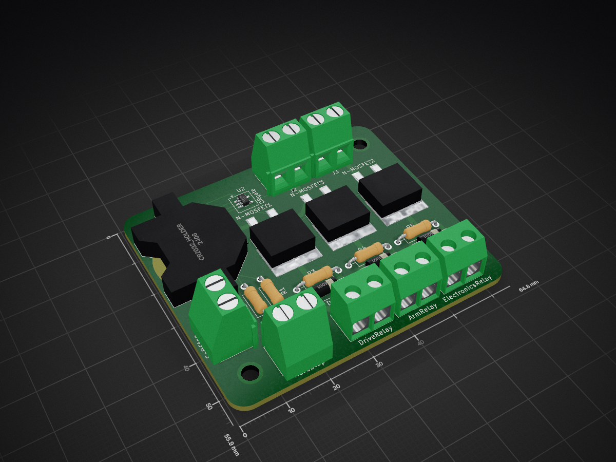
 SaddlebackCollegeRobotics/killswitch_pcb
Hard and soft stop pcb for the rover. The PCB controls the energization of respective relay's coil.
Killswitch is an open-source printed circuit board by SaddlebackCollegeRobotics, from the SaddlebackCollegeRobotics/killswitch_pcb repository on GitHub. It is a 2-layer board of 64.8 × 55.9 mm with 21 parts on 13 nets, routed with 87 tracks and 7 vias.
It is built around the IRFS3806TRLPBF. Its parts include 5 resistors, 5 connectors, 3 diodes and 2 ICs.
Hard and soft stop pcb for the rover. The hard stop cuts power for all subsystems. The soft stop also cuts power but it leaves computing power on. The PCB controls the energization of the Electrical (computing power), Arm, and Drive relay's coil.
The design of the PCB is recorded in osiris_meta #51.
 (02.22.2022)
During testing (osiris_meta #67), the resistors for the coil (500 ohm, 1/4 W) smoked. Using a higher resistance (6k ohm) fixed the smoking issue, but the resistor got warm. The problem can be fixed using higher wattage resistors, but I didn't have time to get them. The resistors were used to limit the current going to the coils as a safety precaution, but the current drawn from the coil is already small, so I opted to not use a resistor and short the endings on the PCB (soldered a wire instead of a resistor).
PCB works as intended without the coil resistors! The 48-V coil relay warms after less than one minute, I read online that this is a normal behaviour of relays, but one minute is too little time.
This is the schematic of how the killswitch was connected to the protection layers already in the rover. Notice that the circuit breaker goes before the relay.

The metal switch contacts of the relays melted together from overheat.
I had connected the 48V battery into the system, and not the 12V battery. After 5 minutes, I noticed the relays were hot. With the design of the killswitch, not having one battery (48 or 12) should not have been an issue. After troubleshooting, I concluded it was the relays and not the design of the PCB. Note that since the beginning, the relays were not reliable. The vendor didn't provide any datasheet and the build of the relay was not very professional. (The relays were bought from a third party in Walmart during the time when the team was discouraged from buying from Amazon).
I replaced the unreliable 48V coil relay with 12V ones that I found on Amazon.

The changes were not made to the PCB itself due to lack of time.
A summary of all changes is in the picture:

| Qty | Value | Footprint | References |
|---|---|---|---|
| 3 | 1N4001 | Diode_THT:D_DO-41_SOD81_P10.16mm_Horizontal | D1, D2, D3 |
| 3 | 500 | Resistor_THT:R_Axial_DIN0207_L6.3mm_D2.5mm_P10.16mm_Horizontal | R3, R4, R5 |
| 3 | IRFS3806TRLPBF | alexisawesome:NChan_MOSFET_IPB026N06NATMA1 | N-MOSFET1, N-MOSFET2, N-MOSFET3 |
| 3 | Screw_Terminal_01x02 | TerminalBlock:TerminalBlock_bornier-2_P5.08mm | J1, J4, J5 |
| 2 | 10K | Resistor_THT:R_Axial_DIN0207_L6.3mm_D2.5mm_P10.16mm_Horizontal | R1, R2 |
| 2 | Screw_Terminal_01x02 | alexisawesome:TerminalBlock_bornier-2_P5.08mm | J2, J3 |
| 1 | CR2032_Holder | alexisawesome:CR2032_Holder_SMD | U1 |
| 1 | HS | alexisawesome:TerminalBlock_bornier-2_P5.08mm | HardStop |
| 1 | LOGO | alexisawesome:SCRoboticsLogo | G*** |
| 1 | ORgate | alexisawesome:SN74AUP1G32DBVT_ORgate | U2 |
| 1 | SS | alexisawesome:TerminalBlock_bornier-2_P5.08mm | SoftStop |
It measures 64.8 × 55.9 mm and has 2 copper layers, 1.6 mm thick.
21 parts, built around the IRFS3806TRLPBF. The full list of its parts is on this page, with links to each part's symbol and footprint where PCBKit's library has them.
From the SaddlebackCollegeRobotics/killswitch_pcb repository on GitHub, at the commit this page was made from: the board is killswitch.kicad_pcb. PCBKit opens the board in the browser, with nothing to install.
Its repository states no licence, so its author keeps all rights: ask SaddlebackCollegeRobotics before reusing the design.
gusmanb/logicanalyzer
24 channel, 100Msps logic analyzer hardware and software

mntmn/amiga2000-gfxcard
MNT VA2000, an Open Source Amiga 2/3/4000 Graphics Card (Zorro II/III), written in Verilog


hackclub/OnBoard
💡 Join 1,000 teenagers and make your first PCB with a $100 grant!

drandyhaas/KiCadRoutingTools
A set of Python/Rust tools to aid routing in KiCad

Arrow-air/project-quiver
Project Quiver documentation, designs, and project artifacts.

