
2 layers55 × 84.4 mm

 sachith-pai/Smart-3-Phase-Energy-Meter3
An esphome/Zigbee based energy meter powered by PZEM-004T V4 and Xiao Esp32 c6
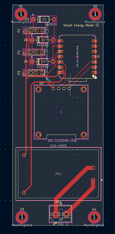
Energy Meter is an open-source printed circuit board by sachith-pai, from the sachith-pai/Smart-3-Phase-Energy-Meter repository on GitHub, published under the MIT licence. It is a 2-layer board of 44 × 107 mm with 15 parts on 19 nets, routed with 67 tracks and 1 via.
It is built around the HLK-5M05. Its parts include 4 connectors, 3 diodes and 2 ICs. It belongs with the ESP32 and RISC-V boards of this library.
An ESPHome-based energy meter powered by PZEM-004T V4 and Seed Studio Xiao ESP32-C6/ESP32-C3
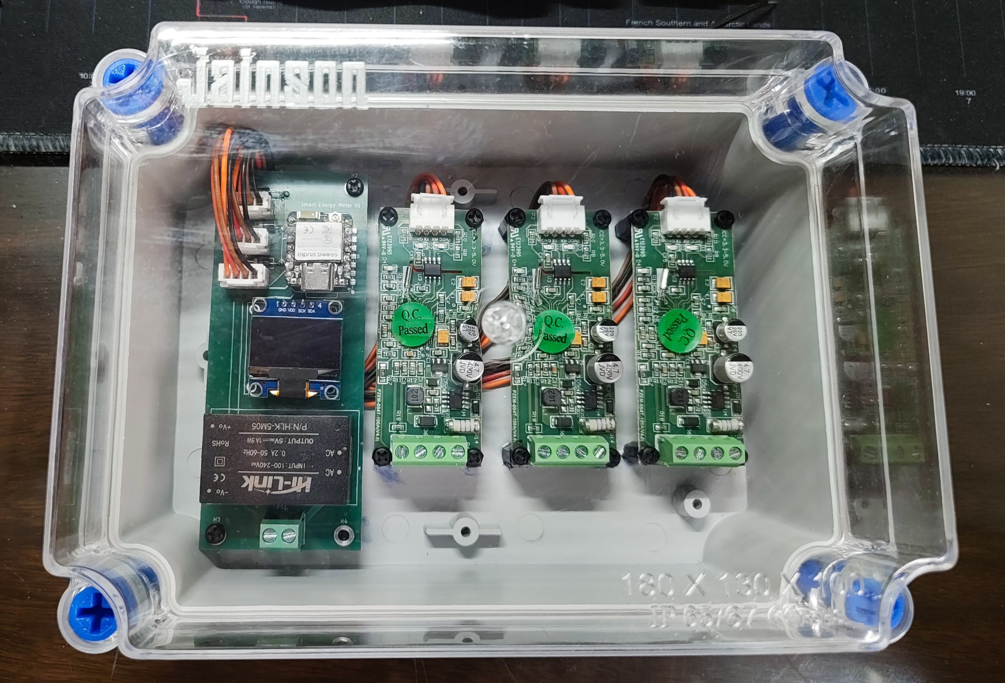
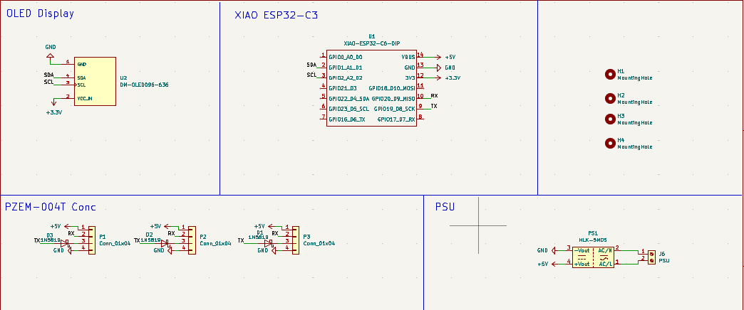
[!NOTE] If ESPHome is unable to read from all three PZEM modules simultaneously, it is because multiple devices prevent the signal from dropping close enough to GND. To fix this, it is recommended to place a 1N5819 Schottky diode on the TX line of each PZEM . Which I have included in the schematics as well as in the PCB
 |
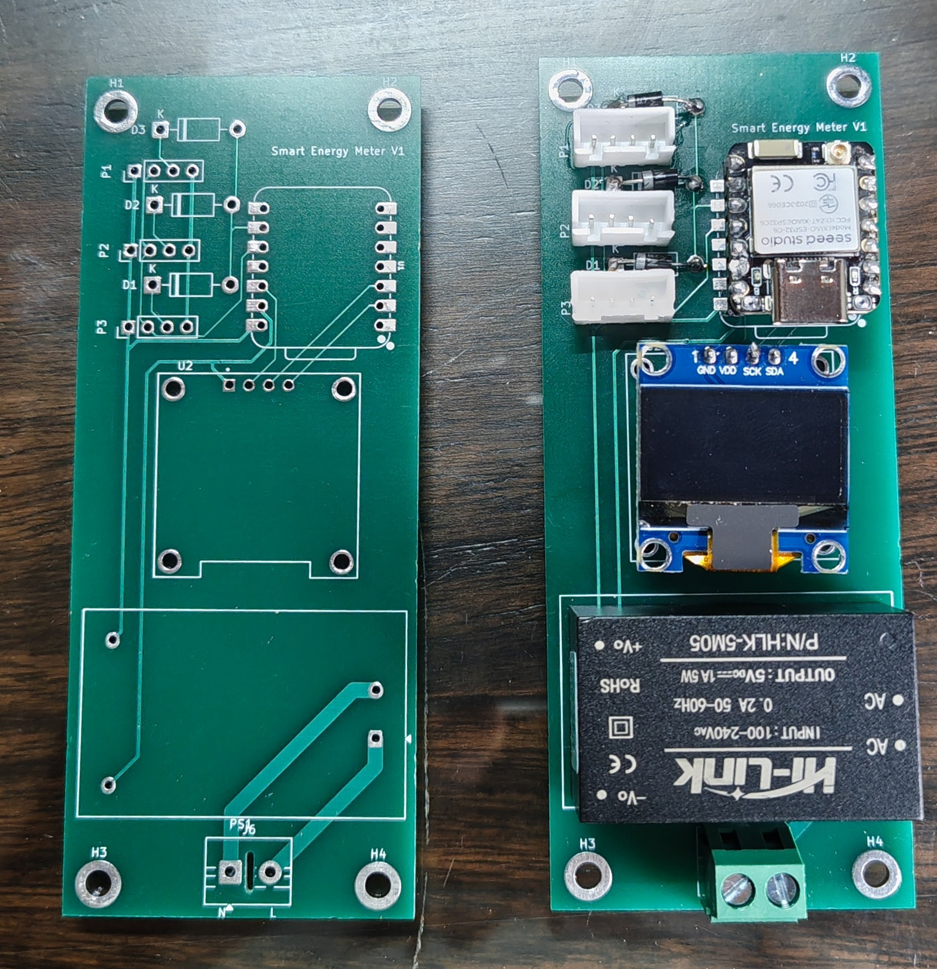 |
[!NOTE] The address can also be changed in ESPHome, but this is recommended
| Phase | Address |
|---|---|
| P1 | 0x01 |
| P2 | 0x02 |
| P3 | 0x03 |
| Qty | Value | Footprint | References |
|---|---|---|---|
| 4 | MountingHole | MountingHole:MountingHole_3.2mm_M3_ISO7380_Pad | H1, H2, H3, H4 |
| 3 | 1N5819 | Diode_THT:D_DO-41_SOD81_P10.16mm_Horizontal | D1, D2, D3 |
| 3 | Conn_01x04 | Connector_PinHeader_2.54mm:PinHeader_1x04_P2.54mm_Vertical | P1, P2, P3 |
| 1 | DM-OLED096-636 | Oled 0.96:MODULE_DM-OLED096-636 | U2 |
| 1 | HLK-5M05 | Converter_ACDC:Converter_ACDC_Hi-Link_HLK-5Mxx | PS1 |
| 1 | LOGO | QR:EM_10X10 | G*** |
| 1 | PSU | TerminalBlock:TerminalBlock_MaiXu_MX126-5.0-02P_1x02_P5.00mm | J6 |
| 1 | XIAO-ESP32-C6-DIP | xiao:XIAO-ESP32-C6-DIP | U1 |

denorath-sys/gridnet
Open hardware powerline mesh communication terminal

Kikkiu17/espiot
A small board built to measure current and voltage of any appliance.


bjkayani/PCB-Reflow-Hot-Plate
The PCB Reflow Hot Plate is a temperature controlled 120 x 70 mm hot plate designed to reflow solder SMD circuit boards.

gmeirelles-ops/esp32-DPTri
Firmware ESP-IDF para a DPSin Board WiFi Triac (rev v1.0.1): relé AC ON/OFF e dimmer TRIAC por porcentagem, controlados pelo app, com pareamento por hold ≥10 s no botão PAIR.

lorinczstefanmihai/BathGuardian
An ESP32-powered monitoring & automation system for humidity, gas levels, temperature, and bathroom safety.

It measures 44 × 107 mm and has 2 copper layers, 1.6 mm thick.
15 parts, built around the HLK-5M05. The full list of its parts is on this page, with links to each part's symbol and footprint where PCBKit's library has them.
From the sachith-pai/Smart-3-Phase-Energy-Meter repository on GitHub, at the commit this page was made from: the board is kicad/Energy Meter.kicad_pcb and its schematic kicad/Energy Meter.kicad_sch. PCBKit opens the board in the browser, with nothing to install.
Its repository publishes it under the MIT licence: you may reuse it on that licence's terms (keep the author's notice, and for a copyleft licence share your changes alike).