2 layers
MashMachine V2.0-Emil
xrayer2000/MashMachine
My own built brewing system for making wonderful beer at home
29 parts1

 bjkayani/PCB-Reflow-Hot-Plate1
The PCB Reflow Hot Plate is a temperature controlled 120 x 70 mm hot plate designed to reflow solder SMD circuit boards.
PCB Reflow Hot Plate is an open-source printed circuit board by bjkayani, from the bjkayani/PCB-Reflow-Hot-Plate repository on GitHub. It is a 2-layer board of 80 × 60 mm with 70 parts on 55 nets, routed with 382 tracks and 75 vias.
It is built around the ESP32-C3-MINI-1, HLK-5M05 and MAX6675ISA+, with the ME6211C33M5G-N, BSS138 and MBR0540 among its other parts. Its parts include 15 resistors, 9 capacitors, 6 diodes, 6 switches and 5 connectors. It belongs with the ESP32 and RISC-V boards of this library.


The PCB Reflow Hot Plate is a temperature controlled 120 x 70 mm hot plate designed to reflow solder SMD circuit boards. This project was started due to a gap in the commercial solutions for a mid sized form factor hot plate.
This project is a work in progress and various elements of it are continually improving and changing. Refer to the build guide for more information including a compatibility table.
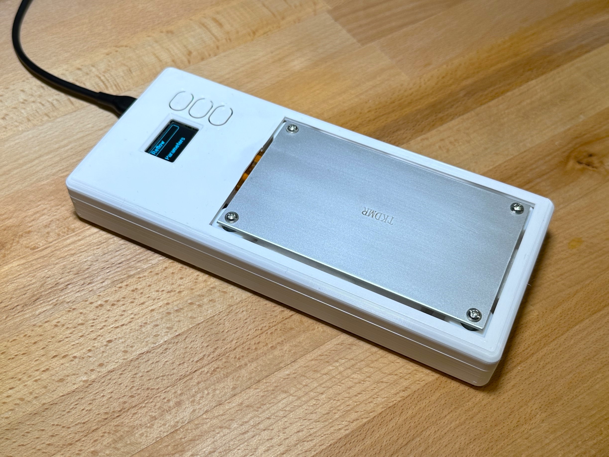
With these considerations in mind, this is the design I came up with. It uses an off the shelf heating plate with an embedded 300W heating element. I designed my own control board that includes everything needed to control the heating plate and can run entirely from mains input.
I went with a small 0.96" OLED display and three buttons as that seems adequate to control the UI. The UI is simple and intuitive yet provides all the functionality needed to operate and customize the hot plate.
Its all packaged in a slim, rectangular 3D printed case that exposes the hot plate provide a window for the display and integrated buttons. The hotplate has insulation placed underneath it to prevent heat loss from the bottom. The case needs to be printed in a relatively temperature resistant material to avoid warping at high temperature.
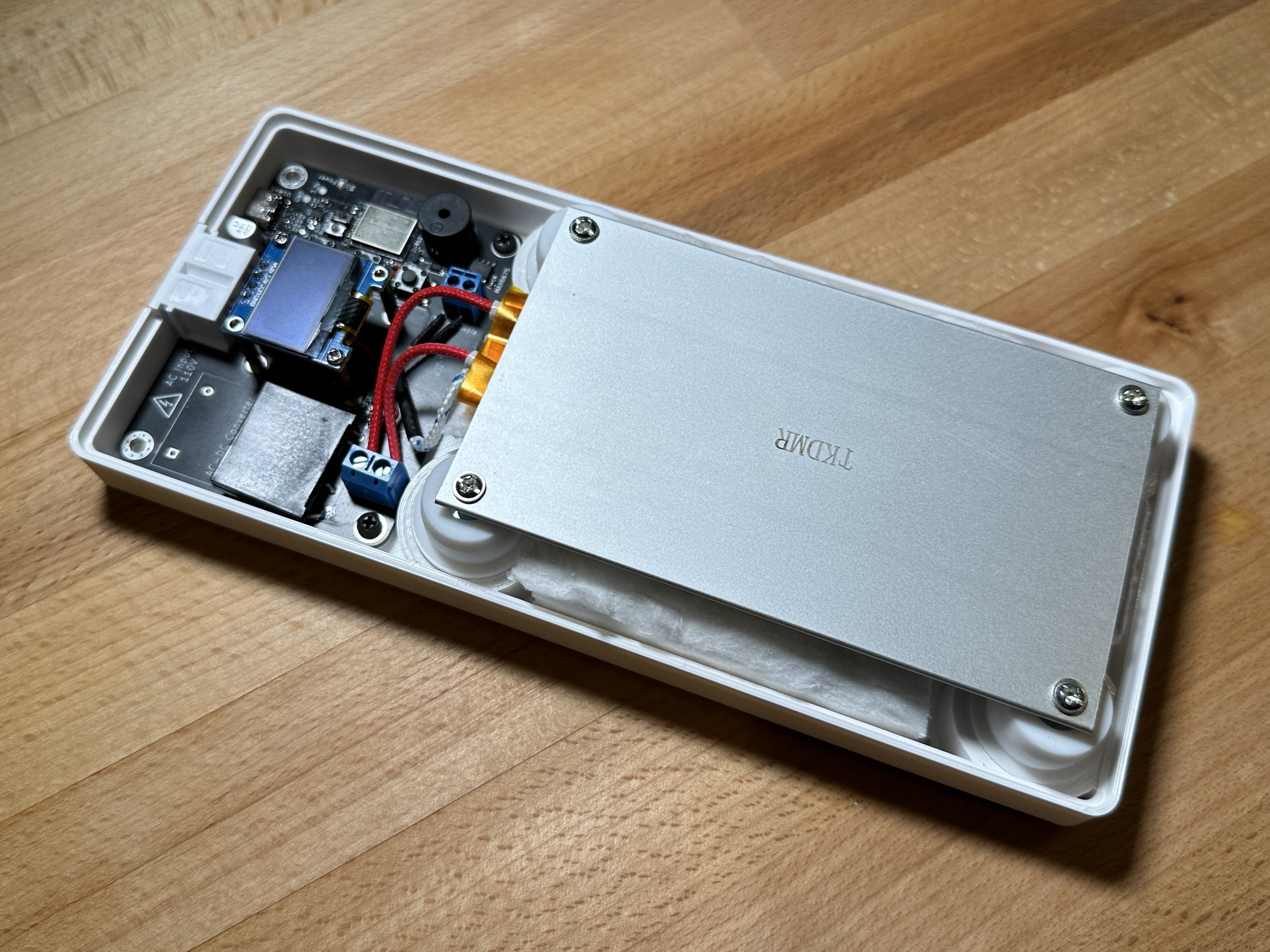
The PCB is designed in KiCAD. Its a 2-layer design and it contains everything needed to run the hot plate with a single mains input. The USB-C port provides power to the DC section and allows for programming the ESP32-C3 microcontroller. The OLED display is on a separate daughter board and mounted using M2 standoffs. A standard 0.96" OLED display module should work although there is some variation in the models avaiable. More information regarding that coming soon.


The code is written in Arduino IDE due to its ease of use and simlicity over PlatformIO and native ESP SDK. The code is split up into multiple files with each file containing functions relating to specific funcionality.
The code is continually under development and I am adding new features regularly. I have also commented the code so that its easy to understand. Feel free to look through the code, file an issue if you encounter one or request features to be added.
I have a lot of features I want to add that are on the road map but I first wanted to get the basic funtionality working and tested. These are listed at the start of the main program file.
The housing is designed in SolidWorks. Its designed as a two part enclosure with a tab and screws to hold the two together. The heating plate comes with silicon feet that fit into the base. The base is raised to be slighly protruding from the top surface and insulation is put underneath to avoid heat dissipation from the bottom.
The latest STL and design files can be found in the CAD folder. The assembly is missing the PCB due to import issues from KiCAD into SolidWorks.


| PCB (HW) | OLED Module | Code (FW) | CAD |
|---|---|---|---|
| Rev 1.0 | SSD1306 0.96" 25.2x26mm AliExpress Link | 1.0 | Housing Top v1 Housing Base v1 |
| Rev 1.1 | SSD1306 0.96" 27.6x27.6mm Amazon Link | 1.0 | Housing Top v2 Housing Base v1 |
| Rev 1.2 | SSD1306 0.96" 27.6x27.6mm Amazon Link | 1.1 | Housing Top v3 Housing Base v2 Light Pipe v1 |
| Rev 1.3 | SSD1306 0.96" 27.6x27.6mm Amazon Link | 1.1 | Housing Top v3 Housing Base v2 Light Pipe v2 |
| Qty | Value | Footprint | References |
|---|---|---|---|
| 9 | 10k | Resistor_SMD:R_0402_1005Metric | R7, R8, R9, R10, R12, R13, R14, R15, R16 |
| 4 | LOGO | LOGO | G***, G***, G***, G*** |
| 4 | MountingHole | MountingHole:MountingHole_2.2mm_M2_Pad | H5, H6, H7, H8 |
| 4 | MountingHole | MountingHole:MountingHole_3.2mm_M3_Pad_Via | H1, H2, H3, H4 |
| 3 | 100n | Capacitor_SMD:C_0402_1005Metric | C2, C6, C9 |
| 3 | 1u | Capacitor_SMD:C_0402_1005Metric | C3, C4, C7 |
| 3 | ~ | pcb-reflow-hot-plate:TL3305AF260QG | SW2, SW3, SW4 |
| 2 | 10R | Resistor_SMD:R_0402_1005Metric | R3, R4 |
| 2 | 10u | Capacitor_SMD:C_0603_1608Metric | C1, C5 |
| 2 | 1k | Resistor_SMD:R_0402_1005Metric | R5, R6 |
| 2 | 5k1 | Resistor_SMD:R_0402_1005Metric | R1, R2 |
| 2 | BSS138 | Package_TO_SOT_SMD:SOT-23 | Q1, Q2 |
| 2 | MBR0540 | Diode_SMD:D_SOD-123 | D2, D3 |
| 1 | 1N4148 | Diode_SMD:D_SOD-123 | D1 |
| 1 | 220u | Capacitor_SMD:C_Elec_6.3x5.8 | C8 |
| 1 | 3.3V | TestPoint:TestPoint_Pad_D1.5mm | TP2 |
| 1 | 5V | TestPoint:TestPoint_Pad_D1.5mm | TP1 |
| 1 | AC In | pcb-reflow-hot-plate:Conn_IEC-C1_AC_Receptacle_2-Pin | J2 |
| 1 | Boot | pcb-reflow-hot-plate:GT-TC034F-H018-L1 | SW1 |
| 1 | Buzzer | pcb-reflow-hot-plate:CMI-9653S-SMT-TR | BZ1 |
| 1 | Buzzer Enable | Jumper:SolderJumper-2_P1.3mm_Bridged_RoundedPad1.0x1.5mm | JP1 |
| 1 | ESP32-C3-MINI-1 | Espressif:ESP32-C3-MINI-1 | U5 |
| 1 | Fuse | Fuse:Fuse_Littelfuse_395Series | F1 |
| 1 | G3MB202PDC12 | pcb-reflow-hot-plate:RELAY_G3MB202PDC12 | K1 |
| 1 | GND | TestPoint:TestPoint_Pad_D1.5mm | TP3 |
| 1 | HLK-5M05 | pcb-reflow-hot-plate:CONV_HLK-5M05 | PS1 |
| 1 | Heater | TerminalBlock_RND:TerminalBlock_RND_205-00001_1x02_P5.00mm_Horizontal | J4 |
| 1 | LED | LED_SMD:LED_0603_1608Metric | D4 |
| 1 | MAX6675 | Package_SO:SOIC-8_3.9x4.9mm_P1.27mm | U3 |
| 1 | ME6211C33M5G-N | Package_TO_SOT_SMD:SOT-23-5 | U2 |
| 1 | OLED Display | Connector_PinHeader_2.54mm:PinHeader_1x04_P2.54mm_Vertical | J3 |
| 1 | RST | TestPoint:TestPoint_Pad_D1.5mm | TP8 |
| 1 | RXD | TestPoint:TestPoint_Pad_D1.5mm | TP5 |
| 1 | Relay LED | LED_SMD:LED_0603_1608Metric | D5 |
| 1 | Reset | pcb-reflow-hot-plate:GT-TC034F-H018-L1 | SW5 |
| 1 | SCL | TestPoint:TestPoint_Pad_D1.5mm | TP7 |
| 1 | SDA | TestPoint:TestPoint_Pad_D1.5mm | TP6 |
| 1 | TXD | TestPoint:TestPoint_Pad_D1.5mm | TP4 |
| 1 | Thermocouple | TerminalBlock_4Ucon:TerminalBlock_4Ucon_1x02_P3.50mm_Horizontal | J5 |
| 1 | USB-C | pcb-reflow-hot-plate:Conn_USB-C_Receptacle_16Pin_Horizontal | J1 |
| 1 | WS2812B | LED_SMD:LED_WS2812B_PLCC4_5.0x5.0mm_P3.2mm | D6 |
xrayer2000/MashMachine
My own built brewing system for making wonderful beer at home


denorath-sys/gridnet
Open hardware powerline mesh communication terminal


OnionDAO-git/oniondao-badge
An open-source, hacker-conference-style electronic badge built around the ESP32-S3-WROOM-1-N8R8 (8 MB flash + 8 MB Octal PSRAM), with swappable RF / audio / storage modules, an e-paper (or TFT) display socket, a secure…


IpinZhu/foc-esc
这是一个基于 STM32G473RC 的实验性三相 PMSM/BLDC 电机控制平台。仓库包含驱动板设计,以及使用 Rust 2024 + Embassy 实现的电流控制型磁场定向控制(FOC)固件。

ikonis/OpenWatts
OpenWatts is a crank-mounted, single-sided cycling power meter built around an ESP32-C3. A bonded strain-gauge bridge and HX711 measure crank torque, while an LSM6DS3 IMU provides cadence and motion wake.
It measures 80 × 60 mm and has 2 copper layers, 1.6 mm thick.
70 parts, built around the ESP32-C3-MINI-1, HLK-5M05, MAX6675ISA+ and ME6211C33M5G-N. The full list of its parts is on this page, with links to each part's symbol and footprint where PCBKit's library has them.
From the bjkayani/PCB-Reflow-Hot-Plate repository on GitHub, at the commit this page was made from: the board is PCB/pcb-reflow-hot-plate/pcb-reflow-hot-plate.kicad_pcb and its schematic PCB/pcb-reflow-hot-plate/pcb-reflow-hot-plate.kicad_sch. PCBKit opens the board in the browser, with nothing to install.
Its repository states no licence, so its author keeps all rights: ask bjkayani before reusing the design.