2 layers23.7 × 19.1 mm
Pmod adapter
ryanhaus/rowan-baja-daq
Data Acquisition system for Rowan University's Baja SAE 2025-2027 team.
19 parts1GPL-3.0

 ryanhaus/rowan-baja-daq1
Data Acquisition system for Rowan University's Baja SAE 2025-2027 team.
Can module is an open-source printed circuit board by ryanhaus, from the ryanhaus/rowan-baja-daq repository on GitHub, published under the GPL-3.0 licence. It is a 2-layer board of 25.4 × 19 mm with 49 parts on 50 nets, routed with 194 tracks and 46 vias.
It is built around the ATA6560-GBQW-N, NID5100GWH and DESD5V0U1BA-7-ES, with the LTST-C170GKT and 1206L050YR among its other parts. Its parts include 14 capacitors, 5 resistors, 5 diodes, 4 connectors and 3 ICs. It belongs with the PIC boards of this library.


The CAN Module is a 1" x 0.75" printed circuit board (PCB) designed in KiCad. All KiCad files are available in the 'pcb' directory.
The board features a 48MHz PIC32 microcontroller, a CAN Transceiver, headers for power and CAN communication, as well as 8 GPIO pins.
Below shows an orthographic top and bottom view of the board:
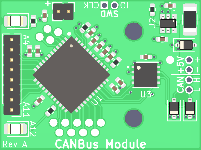
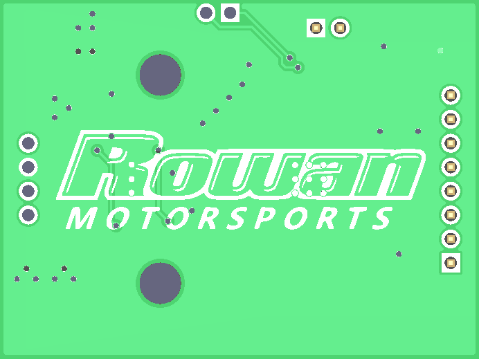
[!NOTE] If more than 8 GPIO pins are required for a particular sensor or module, an I2C GPIO expander can be used, or wires can be soldered to one of the exposed GPIO test points (see here). Alternatively, a larger custom board can be designed, these modules are able to communicate with any CAN-FD compatible device that communicates with a 5V logic level.
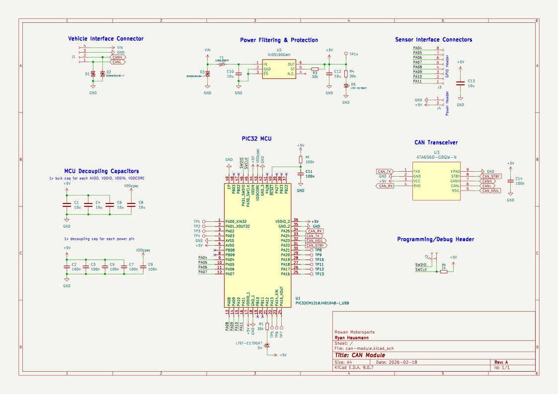
A schematic of the CAN Module is shown below. Higher-quality pdf available here.
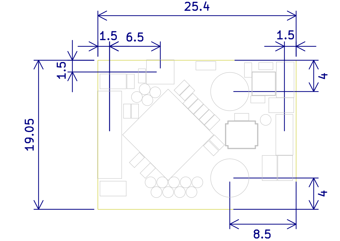
The dimensions below may be of use for designing custom enclosures or daughterboards to be mounted to the CAN Module.
All dimensions are in mm, and the mounting holes are M2. Additionally, the pin headers have 0.05" (1.27mm) hole spacing.
The boards should be powered with +5V DC through the appropriate pins in the vehicle interface.
The total power consumption depends on attached sensors and modules, but 100-200 mA at most will be consumed by the board itself during peak power usage.
[!NOTE] The boards feature reverse polarity protection, a resettable fuse, and ESD protection diodes on all pins within the vehicle interface.
The microcontroller on the CAN Module is the PIC32CM1216JH01048-I/U5B, an inexpensive and tiny 32-bit ARM microcontroller that operates at 48MHz with 128KB of flash and 16KB of RAM, as well as an embedded hardware CAN controller. See the datasheet here.

The CAN Transceiver on the CAN Module is the ATA6560-GBQW-N. See the datasheet here.

There are two indication LEDs present on the CAN Module. One LED is a power indicator LED and is not configurable. The other is configurable and has the cathode connected through a 30k resistor to the PA12 pin on the microcontroller. Each LED has 5V at the anode.
All pins on the CAN Module operate at 5V logic levels by default. There are two distinct sets of pins on the board that serve different purposes, the sensor interface and the vehicle interface, as described and labelled below.
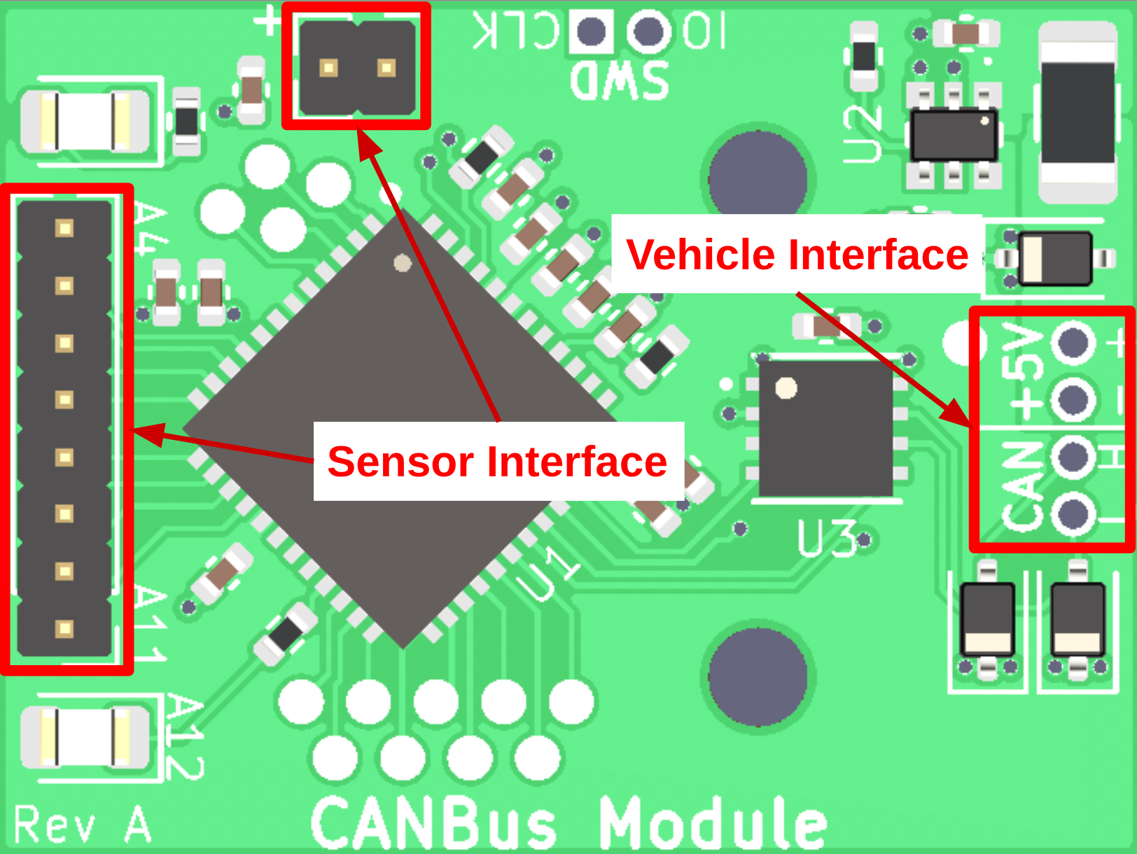
[!WARNING] The headers use 0.05" (1.27mm) hole spacing for space conservation, not the more common 0.1" (2.54mm) spacing.
The sensor interface is the set of 8 GPIO and 2 output power pins located on the left side of the board. These pins are intended to provide power to and communicate with some sensor or module, or a custom-designed daughterboard which mounts on top of the CAN Module PCB.
There are two distinct pin headers in the sensor interface, one being 2 pins, and the other being 8 pins. These are the output power and communication headers, respectively.
The output power header has a positive pin (+5V) and a negative pin (GND), which is labelled appropriately on the board.
The communication header has 8 GPIO pins which are directly connected to GPIO pins on the microcontroller. The pins included in this header include GPIO pins PA4 through PA11 from the microcontroller in sequential order, as labelled on the board. These pins were selected because every one of them is capable of acting as a communication interface pin for the SERCOM peripheral on the microcontroller, see the datasheet (Table 4-2) for more info.
[!WARNING] These pins do not have ESD diodes, series resistors, or short circuit protection (other than what is provided by the microcontroller's GPIO pins).
[!NOTE] Some of these pins are powered by AVDD and some are powered by VDDIO. While VDDIO can be changed to 3.3V to use 3.3V logic, AVDD must remain 5V. A future revision of this board could take this into consideration and only expose pins powered by VDDIO, so that 3.3V logic can be achieved without external logic level converters. Another solution could be to power the entire chip by 3.3V and use an ATA6561 instead of the ATA6560, since the former is able to communicate with 3.3V microcontrollers.
The vehicle interface is the set of 2 communication and 2 input power pins located on the right side of the board. These pins are intended to provide power to the CAN Module board and allow for communication between the board and the rest of the vehicle via the shared CAN Bus.
The pins are organized as a single 4-pin header.
13 extra GPIO pins are exposed from the microcontroller and can be used. See the screenshot below to see all labelled test points.
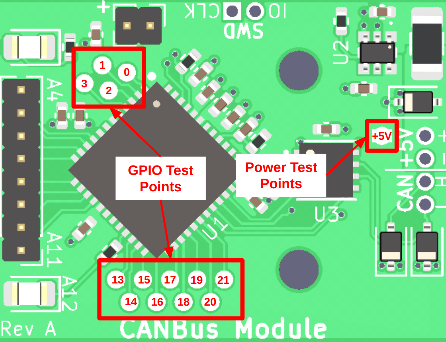
[!NOTE] All GPIO test points are exposed from Port A, so it is not explicitly labelled in the screenshot. For example, the point labelled '13' maps to PA13, '14' to PA14, etc.
[!NOTE] In addition to GPIOs, there is also a test point for +5V. This test point is after all power filtering & fusing, so it may be helpful for debugging power issues.
Two serial-wire debug (SWD) pins are exposed and labelled on the back of the board. A SWD-capable interface will be required to program the boards.
[!NOTE] This is TBD, the boards have not been manufactured yet.
In order to interface with other devices (i.e., other CAN Modules), they must be wired on the same shared CAN Bus. An example layout is shown below:
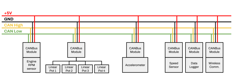
Note that every module shares the same four wires that are routed throughout the vehicle. This topology helps significantly reduce the amount of wire required, time spent routing wire, and helps decentralize devices to minimize single points of failure.
Also note that CAN Bus Modules generally do not exist on their own, they will probably need some other attached device or sensor to either provide or process data on the bus.
See here for more info on CAN Bus.
[!WARNING] Make sure that the CAN bus is properly terminated, see here for more info.
After changes are made to the project, KiBot (must be installed) can be used to automatically create renders of the schematic and PCB used in this documentation.
Navigate to the pcb directory, and run the following:
$ kibotThis command will automatically run the DRC and generate renders.
See can-module.kibot.yaml for the configuration.
| Qty | Value | Footprint | References |
|---|---|---|---|
| 14 | TestPoint | TestPoints:TestPoint_Pad_D1.0mm_TightSpacing | TP1, TP2, TP3, TP4, TP5, TP6, TP7, TP8, TP9, TP10, TP11, TP12, TP13, TP14 |
| 7 | 100n | Capacitor_SMD:C_0402_1005Metric | C2, C3, C5, C7, C9, C11, C14 |
| 7 | 10u | Capacitor_SMD:C_0402_1005Metric | C1, C4, C6, C8, C10, C12, C13 |
| 3 | 30k | Resistor_SMD:R_0402_1005Metric | R1, R3, R4 |
| 3 | DESD5V0U1BA-7 | Diode_SMD:D_SOD-323 | D1, D2, D3 |
| 2 | Conn_01x02_Socket | Connector_PinHeader_1.27mm:PinHeader_1x02_P1.27mm_Vertical | J2, J4 |
| 2 | LTST-C170GKT | LED_SMD:LED_0805_2012Metric | D4, D5 |
| 1 | 100k | Resistor_SMD:R_0402_1005Metric | R2 |
| 1 | 1206L050YR | Fuse:Fuse_1206_3216Metric | F1 |
| 1 | 1k | Resistor_SMD:R_0402_1005Metric | R5 |
| 1 | ATA6560-GBQW-N | ATA6560-GBQW-N:VDFN8_3X3_MCH | U3 |
| 1 | Conn_01x04_Socket | Connector_PinHeader_1.27mm:PinHeader_1x04_P1.27mm_Vertical | J1 |
| 1 | Conn_01x08_Socket | Connector_PinHeader_1.27mm:PinHeader_1x08_P1.27mm_Vertical | J3 |
| 1 | LOGO | Logos:RowanMotorsports | G*** |
| 1 | NID5100GWH | NID5100GWH:NID5100GWH | U2 |
| 1 | PIC32CM1216JH01048-I_U5B | PIC32CM1216JH01048-I/U5B:QFN50P700X700X90-49N-D | U1 |
The 47 most common of 49 parts.
ryanhaus/rowan-baja-daq
Data Acquisition system for Rowan University's Baja SAE 2025-2027 team.

ryanhaus/rowan-baja-daq
Data Acquisition system for Rowan University's Baja SAE 2025-2027 team.

ryanhaus/rowan-baja-daq
Data Acquisition system for Rowan University's Baja SAE 2025-2027 team.

ryanhaus/rowan-baja-daq
Data Acquisition system for Rowan University's Baja SAE 2025-2027 team.

ryanhaus/rowan-baja-daq
Data Acquisition system for Rowan University's Baja SAE 2025-2027 team.

ageppert/SAO_Demo_Controller
A small inline SAO with an RP2040 used to demo SAOs that require smarts, but don't have it built-in.

ryanhaus/sandbox
Sandbox area for small tests and projects that don't constitute a full repo

cdg66/FUSB302_PCB
Yet an other FUSB302 breakout board. I did it using only std kicad lib so it is ready to be implemented in your own project.


laurapreidewe/Agriculture-VCU_v1
STM32 based Vehicle control unit (VCU) PCB for agricultural machinery. Made with KiCad 8, now updated to KiCad 10

laurapreidewe/Agriculture-VCU_v2
Vehicle control unit PCB for agricultural robots and machineries, built around Nuvoton M467HJHAN. Designed in KiCad 8 and updated to KiCad 10, with Ethernet, CAN, UART, ADC/DAC, PWM, and six relay channels.

It measures 25.4 × 19 mm and has 2 copper layers, 1.6 mm thick.
49 parts, built around the ATA6560-GBQW-N, NID5100GWH, DESD5V0U1BA-7-ES and LTST-C170GKT. The full list of its parts is on this page, with links to each part's symbol and footprint where PCBKit's library has them.
From the ryanhaus/rowan-baja-daq repository on GitHub, at the commit this page was made from: the board is can-module/pcb/can-module.kicad_pcb and its schematic accelerometer-board/pcb/accelerometer-board.kicad_sch. PCBKit opens the board in the browser, with nothing to install.
Its repository publishes it under the GPL-3.0 licence: you may reuse it on that licence's terms (keep the author's notice, and for a copyleft licence share your changes alike).