2 layers11 × 25 mm
Temperature a1
ruuvi/connector
Ruuvi Connector is a standardised expansion connector and cable system that takes sensor prototyping to the next level. Compatible connectors will be found on many upcoming Ruuvi products.
7 parts4

 ruuvi/connector4
Ruuvi Connector is a standardised expansion connector and cable system that takes sensor prototyping to the next level. Compatible connectors will be found on many upcoming Ruuvi products.
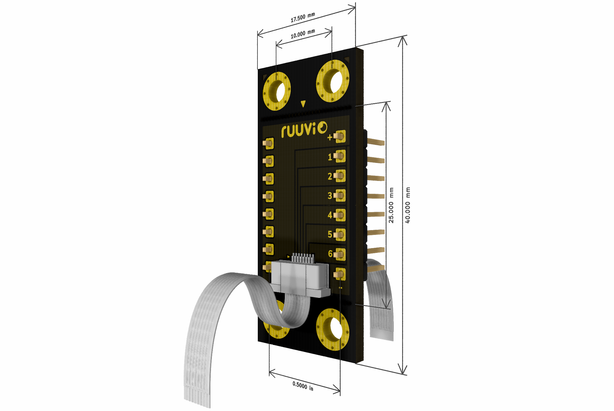
Connector breakout a1 is an open-source printed circuit board by ruuvi, from the ruuvi/connector repository on GitHub. It is a 2-layer board of 17.5 × 40 mm with 18 parts on 16 nets, routed with 13 tracks and 0 vias.
It belongs with the interfaces and adapters boards of this library.
Ruuvi Connector is a standardised expansion connector and cable system that takes sensor prototyping to the next level. Compatible connectors will be found on many upcoming Ruuvi products.
There are many ways on how to use the Ruuvi Connector system:
Ruuvi Connector is compatible with 4-pin (2 signals + VDD + GND) prototyping systems such as Seeed Studio Grove, Sparkfun Qwiic, Adafruit STEMMA, DFRobot Gravity and more.
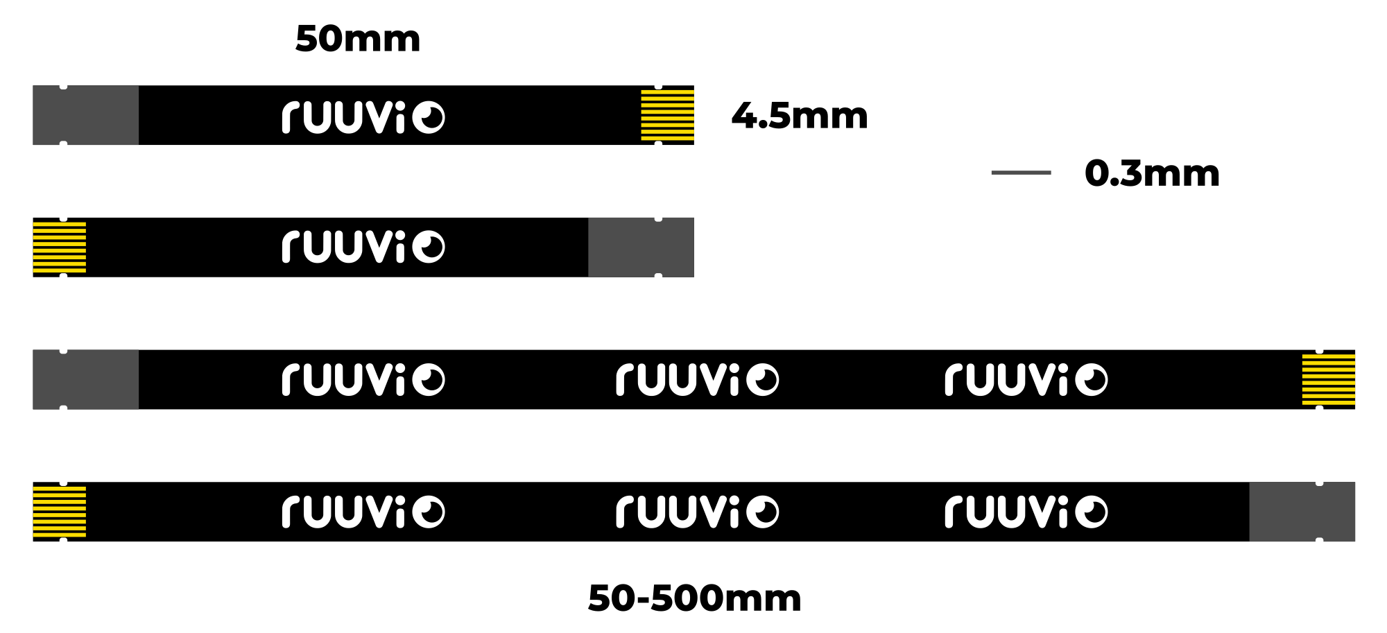
Ruuvi Connector cables have 8 pins (6 signals + VDD + GND). This allows using not just simple I2C sensors but also more powerful SPI sensors equipped with interrupt signals.
Note that on RuuviTags that have Ruuvi Connectors available, pins 2 and 3 are shared with internal I2C sensors. Also pin 7 is connected to TMP117 temperature sensor's interrupt signal (if a TMP117 is populated) but because the interrupt pin is an open-drain output and because it's not active in the Ruuvi firmware by default, it doesn't reserve the pin and it can be safely used for other purposes as long as TMP117 isn't configured to pull it down.
Default FPC connector is AFC07-S08ECA-00.
All the design files in this repository are licensed using Attribution-ShareAlike 4.0 International (CC BY-SA 4.0). Copyright: Ruuvi Innovations Ltd (Oy). Neither the name of the Ruuvi nor the names of its contributors may be used to endorse or promote products derived from this project without a specific prior written permission. While unofficial products should not have "Ruuvi" in their name, it's okay to describe your product in relation to the Ruuvi projects. More info: license@ruuvi.com.
| Qty | Value | Footprint | References |
|---|---|---|---|
| 4 | MountingHole | ruuvitag:MountingHole_3.2mm_M3_Pad_Via | H1, H2, H5, H6 |
| 2 | 27 x 0.4mm NPTH | connector:BreakoutHoles | H3, H4 |
| 2 | LOGO | connector:BreakoutLabels | G***, G*** |
| 2 | LOGO | connector:BreakoutPlus | G***, G*** |
| 2 | LOGO | connector:BreakoutMinus | G***, G*** |
| 2 | Ruuvi Connector Horizontal | connector:RUUVI_CONNECTOR_FFC | J1, J4 |
| 2 | Ruuvi Connector Pin Header | connector:RUUVI_CONNECTOR_8PIN_HEADER | J2, J3 |
| 1 | LOGO | connector:BreakoutBoardA1 | G*** |
| 1 | LOGO | ruuvi:ruuvinegalogo-8mm-mask | G*** |
ruuvi/connector
Ruuvi Connector is a standardised expansion connector and cable system that takes sensor prototyping to the next level. Compatible connectors will be found on many upcoming Ruuvi products.


VoronDesign/Voron-Hardware
Cool Hardware designed by the Voron Design group


hackclub/OnBoard
💡 Join 1,000 teenagers and make your first PCB with a $100 grant!

VoronDesign/Voron-Tap
Tap is a nozzle-based z-probe for the V2 and Trident printer designs. The entire toolhead moves to trigger an optical switch. Tap offers many advantages:

Luos-io/luos_engine
Open-source and real-time orchestrator for cyber-physical-systems, to easily design, test and deploy embedded applications and digital twins.


Twotoz/C5VRX
Ultra-minimal, zero-CPU 5.8 GHz analog FPV video receiver using ESP32-C5 Wi-Fi 6 PHY MODEM_DIAG, BitScrambler WBFM demodulation & resistor DAC CVBS
It measures 17.5 × 40 mm and has 2 copper layers, 1.6 mm thick.
18 parts. The full list of its parts is on this page, with links to each part's symbol and footprint where PCBKit's library has them.
From the ruuvi/connector repository on GitHub, at the commit this page was made from: the board is connector-breakout-a1/connector-breakout-a1.kicad_pcb and its schematic temperature-a1/temperature-a1.kicad_sch. PCBKit opens the board in the browser, with nothing to install.
Its repository states no licence, so its author keeps all rights: ask ruuvi before reusing the design.