2 layers107 × 111 mm
Encoder SPI AS5047P panel
runger1101001/Magnetic_Encoders
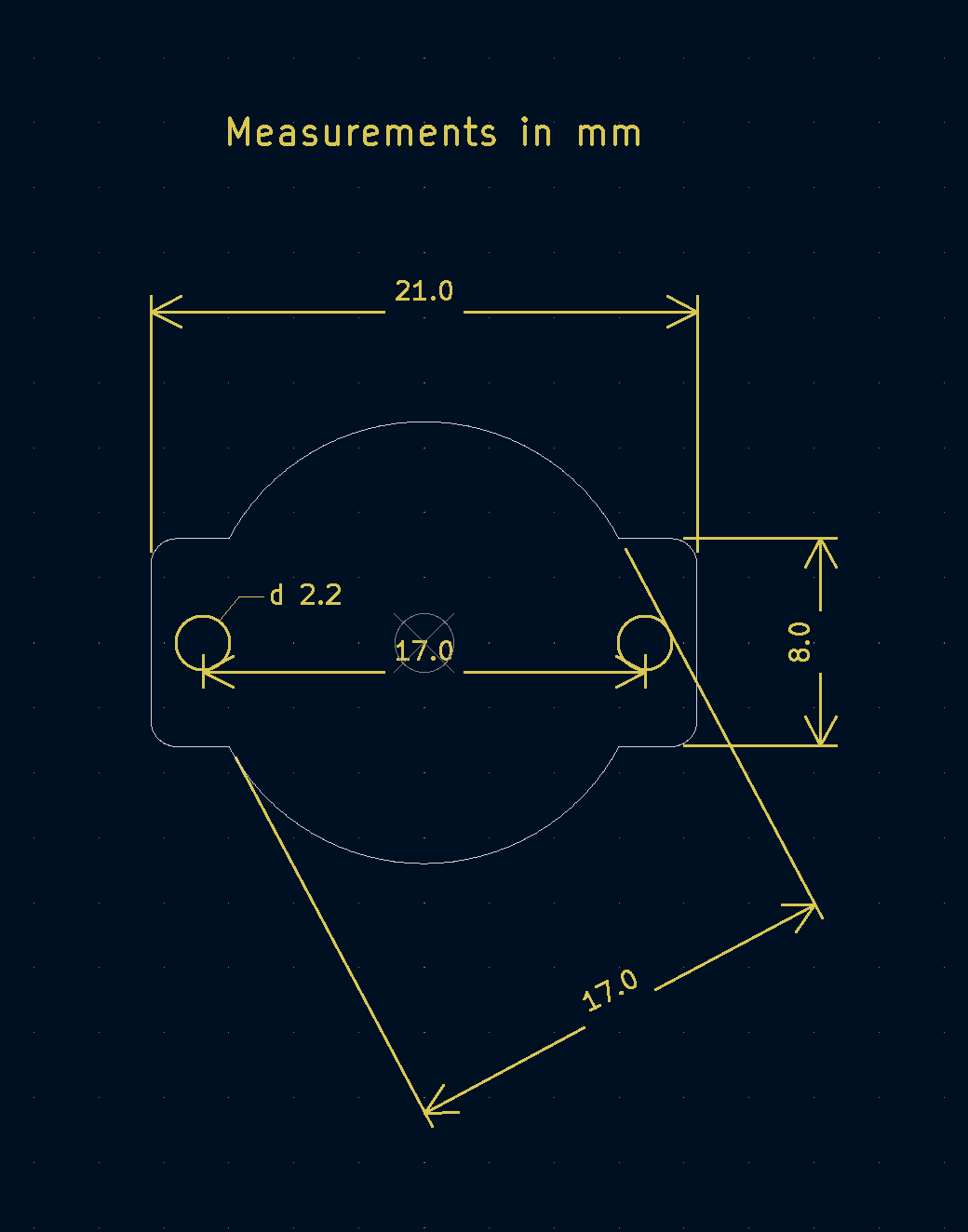
Small (21x17mm) board for the SC60228 magnetic absolute angle sensor.
491 parts11

 runger1101001/Magnetic_Encoders11
Small (21x17mm) board for the SC60228 magnetic absolute angle sensor.
Encoder I2C AS5600 Panel is an open-source printed circuit board by runger1101001, from the runger1101001/Magnetic_Encoders repository on GitHub. It is a 2-layer board of 131 × 111 mm with 741 parts on 200 nets, routed with 1,100 tracks and 250 vias.
Its parts include 75 resistors, 50 capacitors, 50 connectors, 25 ICs and 25 diodes.
Small (21x17mm) board for the SC60228 magnetic absolute angle sensor.
For use in motor control or robotics applications, the sensor measures the orientation (angle in the plane) of a nearby diametrically magnetized magnet.
That sounds more complicated than using it really is, so lets describe it another way:
| Back of board | Front of board |
|---|---|
with SH 1.0 connector  | with sensor  |
Datasheet of the sensor: https://semiment.com/wp-content/uploads/2021/04/SC60228_EN-VA1.0.pdf
You may be able to buy some here:

Or you could make one - it is open source, you will find gerber files and BOM in the repo, and design files for KiCad 6.
The sensor has to be precisely positioned near the magnet. The magnet should be precisely on-axis and in-plane (no wobble!). The sensor should be mounted with an air-gap of about 0.5mm to the magnet.
Taking the time to mount the magnet and sensor board carefully will improve the accuracy and smoothness of your readings.
The sensor has an SPI interface:
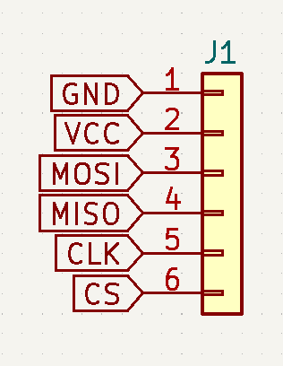
The SPI interface is available on a JST-SH 6-pin socket. Pre-made cables are available cheaply on AliExpress and other sources.
You may connect VCC to either 3.3V or 5V.
Connect the other lines (MOSI, MISO, CLK and CS) to the respective counterparts on your MCU board.
Note: The sensor board does not pull the CS line up.
SPI interface:
See datasheet for details, or use an existing software driver.
:warning: Note: cable length, shielding (or lack thereof) and environmental noise may limit performance to significantly less than the 10MHz maximum.
The sensor can be used with any appropriate SPI driver.
The author uses it with Arduino-compatible MCU boards and the SimpleFOC library.
A driver for the sensor for Arduino and SimpleFOC can be found here: SimpleFOC drivers library
v1.0: 21 x 17 x 4mm (1.6mm PCB)
Pre-made JST SH 1.0 cables are available. When buying cables with two plugs, choose the type that is called "reverse connection" - where the pins on both ends of the cable have the same order.
Some links to compatible cables / breakout boards:
| Qty | Value | Footprint | References |
|---|---|---|---|
| 460 | NPTH | NPTH | KiKit_MB_100_1, KiKit_MB_100_2, KiKit_MB_100_3, KiKit_MB_100_4, KiKit_MB_101_1, KiKit_MB_101_2, KiKit_MB_101_3, KiKit_MB_101_4, KiKit_MB_101_5, KiKit_MB_101_6, KiKit_MB_101_7, KiKit_MB_102_1, KiKit_MB_102_2, KiKit_MB_102_3, KiKit_MB_102_4, KiKit_MB_102_5 +444 |
| 50 | 5k1 | Resistor_SMD:R_0603_1608Metric | R2, R2, R2, R2, R2, R2, R2, R2, R2, R2, R2, R2, R2, R2, R2, R2 +34 |
| 50 | MountingHole_Pad | MountingHole:MountingHole_2.2mm_M2_ISO7380_Pad | H1, H1, H1, H1, H1, H1, H1, H1, H1, H1, H1, H1, H1, H1, H1, H1 +34 |
| 25 | 100nF | Capacitor_SMD:C_0603_1608Metric | C2, C2, C2, C2, C2, C2, C2, C2, C2, C2, C2, C2, C2, C2, C2, C2 +9 |
| 25 | 10uF | Capacitor_SMD:C_0603_1608Metric | C1, C1, C1, C1, C1, C1, C1, C1, C1, C1, C1, C1, C1, C1, C1, C1 +9 |
| 25 | 2k2 | Resistor_SMD:R_0603_1608Metric | R1, R1, R1, R1, R1, R1, R1, R1, R1, R1, R1, R1, R1, R1, R1, R1 +9 |
| 25 | AS5600L | Package_SO:SOIC-8_3.9x4.9mm_P1.27mm | IC1, IC1, IC1, IC1, IC1, IC1, IC1, IC1, IC1, IC1, IC1, IC1, IC1, IC1, IC1, IC1 +9 |
| 25 | Conn_01x03 | Connector_PinHeader_2.54mm:PinHeader_1x03_P2.54mm_Vertical | J3, J3, J3, J3, J3, J3, J3, J3, J3, J3, J3, J3, J3, J3, J3, J3 +9 |
| 25 | Conn_01x04 | Connector_JST:JST_SH_SM04B-SRSS-TB_1x04-1MP_P1.00mm_Horizontal | J1, J1, J1, J1, J1, J1, J1, J1, J1, J1, J1, J1, J1, J1, J1, J1 +9 |
| 25 | LED green | LED_SMD:LED_0603_1608Metric | D1, D1, D1, D1, D1, D1, D1, D1, D1, D1, D1, D1, D1, D1, D1, D1 +9 |
| 6 | Fiducial | Fiducial | KiKit_FID_B_1, KiKit_FID_B_2, KiKit_FID_B_3, KiKit_FID_T_1, KiKit_FID_T_2, KiKit_FID_T_3 |
runger1101001/Magnetic_Encoders
Small (21x17mm) board for the SC60228 magnetic absolute angle sensor.

runger1101001/Magnetic_Encoders
Small (21x17mm) board for the SC60228 magnetic absolute angle sensor.

runger1101001/Magnetic_Encoders
Small (21x17mm) board for the SC60228 magnetic absolute angle sensor.

runger1101001/Magnetic_Encoders
Small (21x17mm) board for the SC60228 magnetic absolute angle sensor.

runger1101001/Magnetic_Encoders
Small (21x17mm) board for the SC60228 magnetic absolute angle sensor.

runger1101001/Magnetic_Encoders
Small (21x17mm) board for the SC60228 magnetic absolute angle sensor.

runger1101001/Magnetic_Encoders
Small (21x17mm) board for the SC60228 magnetic absolute angle sensor.

runger1101001/Magnetic_Encoders
Small (21x17mm) board for the SC60228 magnetic absolute angle sensor.

runger1101001/Magnetic_Encoders
Small (21x17mm) board for the SC60228 magnetic absolute angle sensor.

runger1101001/Magnetic_Encoders
Small (21x17mm) board for the SC60228 magnetic absolute angle sensor.

runger1101001/Magnetic_Encoders
Small (21x17mm) board for the SC60228 magnetic absolute angle sensor.

runger1101001/Magnetic_Encoders
Small (21x17mm) board for the SC60228 magnetic absolute angle sensor.

Tessavana/Soft-interfaces-files
Sharing all circuit, PCB, code and design files to be able to replicate EOP soft interfaces

pris-digital/ManhattanBreakoutBoards-Panelized
A collection of breakout boards for manhattan style prototyping

johannesloetzsch/pillbus
Simple and configurable bus controllers based on STM32.


rraider/Seminarkurs2021
Entwicklung eines turingvollständigen, primitiven Microcontroller in der Software Digital


ytsurui/dcc-funcdecoder-pcb-t0507d
NMRA DCC Decoder Circuit Diagram / PCB Design Data for TOMIX 0507/0773

nikolafilip/nibble
A 4-bit computer built from individual transistors, in public. No integrated circuits. AI-designed, hand-soldered.
It measures 131 × 111 mm and has 2 copper layers, 1.6 mm thick.
741 parts. The full list of its parts is on this page, with links to each part's symbol and footprint where PCBKit's library has them.
From the runger1101001/Magnetic_Encoders repository on GitHub, at the commit this page was made from: the board is Encoder_I2C_AS5600/Encoder_I2C_AS5600_Panel.kicad_pcb. PCBKit opens the board in the browser, with nothing to install.
Its repository states no licence, so its author keeps all rights: ask runger1101001 before reusing the design.