

2 layers50 × 50 mm
T85-with driver and poe
cnlohr/ethertiny
A firmware-only half-duplex 10Base-T implementation for AVRs
41 parts133

 rsedak/attiny85_I2C_RGB_LED_v2.11
Purpose of ATtiny85 I2C RGB LED module is student education. It is published under Attribution-ShareAlike 4.0 International (CC BY-SA 4.0) license. I hope you will enjoy it.
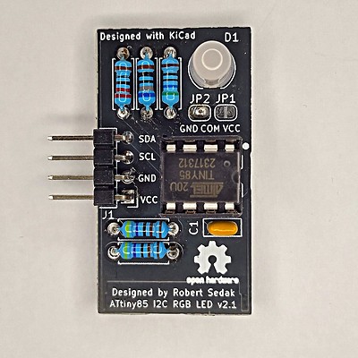
Attiny85 I2C RGB LED v2.1 is an open-source printed circuit board by rsedak, from the rsedak/attiny85_I2C_RGB_LED_v2.1 repository on GitHub. It is a 2-layer board of 20 × 37 mm with 12 parts on 12 nets, routed with 62 tracks and 0 vias.
It is built around the ATTINY85-15M. Its parts include 5 resistors, 1 capacitor, 1 IC, 1 diode and 1 connector. It belongs with the lEDs and displays boards and the AVR (ATmega, ATtiny) boards of this library.
Purpose of ATtiny85 I2C RGB LED module is student education. It shows how to controll RGB via I2C protocol.
Robert Sedak made a video with example programmed in Arduino IDE with ATtiny85 support:
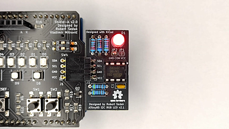
You can download example for Arduino IDE from here.
This project is designed using Open Source KiCad. Design files are located in the design_files folder. You can see the schematic.
You can download gerber files from here.
This project can be programmed using the Open Source Arduino. ATTinyCore by Spence Konde was used to program ATtiny85 in Arduino IDE. Arduino example is located in examples folder.
Attribution-ShareAlike 4.0 International (CC BY-SA 4.0)
You are free to:
This license is acceptable for Free Cultural Works.
Under the following terms:
No additional restrictions — You may not apply legal terms or technological measures that legally restrict others from doing anything the license permits.
Reference Designs ARE PROVIDED "AS IS" AND "WITH ALL FAULTS". Authors DISCLAIMS ALL OTHER WARRANTIES, EXPRESS OR IMPLIED, REGARDING PRODUCTS, INCLUDING BUT NOT LIMITED TO, ANY IMPLIED WARRANTIES OF MERCHANTABILITY OR FITNESS FOR A PARTICULAR PURPOSE. Authors may make changes to specifications and product descriptions at any time, without notice. The Customer must notrely on the absence or characteristics of any features or instructions marked "reserved" or "undefined." Authors reservesthese for future definition and shall have no responsibility whatsoever for conflicts or incompatibilities arising from future changes to them. The product information on the Web Site or Materials is subject to change without notice. Do not finalize a design with this info.
| Qty | Value | Footprint | References |
|---|---|---|---|
| 2 | 4.7K | Resistor_THT:R_Axial_DIN0207_L6.3mm_D2.5mm_P7.62mm_Horizontal | R4, R5 |
| 2 | 560R | Resistor_THT:R_Axial_DIN0207_L6.3mm_D2.5mm_P7.62mm_Horizontal | R1, R3 |
| 2 | SolderJumper_2_Open | Jumper:SolderJumper-2_P1.3mm_Open_RoundedPad1.0x1.5mm | JP1, JP2 |
| 1 | 0.1uF | Capacitor_THT:C_Rect_L4.6mm_W2.0mm_P2.50mm_MKS02_FKP02 | C1 |
| 1 | 620R | Resistor_THT:R_Axial_DIN0207_L6.3mm_D2.5mm_P7.62mm_Horizontal | R2 |
| 1 | ATtiny85 | Package_DIP:DIP-8_W7.62mm | U1 |
| 1 | Conn_01x04_Male | Connector_PinHeader_2.54mm:PinHeader_1x04_P2.54mm_Horizontal | J1 |
| 1 | LED_RCGB | LED_THT:LED_D5.0mm-4_RGB | D1 |
The 11 most common of 12 parts.
cnlohr/ethertiny
A firmware-only half-duplex 10Base-T implementation for AVRs


Guiimartinho/routeai
LLM-Powered Electronic Design Automation Platform for PCB Design

rallekralle11/Tinyreflow
Inspired by afterearthltd's reflow plate, but using fewer and simpler components.

aleh/MIDIMonkey
Listens to MIDI messages on one pin and triggers drums on the others

It measures 20 × 37 mm and has 2 copper layers, 1.6 mm thick.
12 parts, built around the ATTINY85-15M. The full list of its parts is on this page, with links to each part's symbol and footprint where PCBKit's library has them.
From the rsedak/attiny85_I2C_RGB_LED_v2.1 repository on GitHub, at the commit this page was made from: the board is design_files/attiny85_I2C_RGB_LED_v21.kicad_pcb and its schematic design_files/attiny85_I2C_RGB_LED_v21.kicad_sch. PCBKit opens the board in the browser, with nothing to install.
Its repository states no licence, so its author keeps all rights: ask rsedak before reusing the design.