2 layers50 × 50 mm
T85-with driver and poe
cnlohr/ethertiny
A firmware-only half-duplex 10Base-T implementation for AVRs
41 parts133
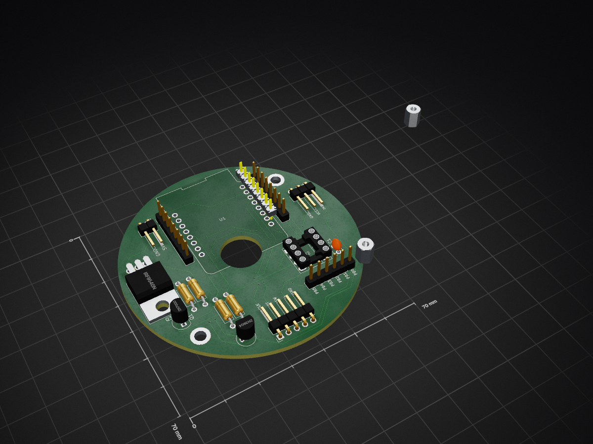
 WebmasterTD/CastVolumeKnob25
Hardware Volume Knob for Google Cast devices
CastVolumeKnob is an open-source printed circuit board by WebmasterTD, from the WebmasterTD/CastVolumeKnob repository on GitHub. It is a 2-layer board with 18 parts on 23 nets, routed with 205 tracks and 19 vias.
It is built around the ATTINY85-20PU, ATTINY85-15M and IRF9540NS. Its parts include 6 connectors, 4 resistors, 3 transistors, 2 ICs and 1 capacitor. It belongs with the AVR (ATmega, ATtiny) boards of this library.


is hardware volume control for Chromecast Audio devices, based on the ESP8266 microcontroller using micropython.
For controlling the volume on Chromecast devices you need to use your phone. - it is clumsy, not very intuitive.
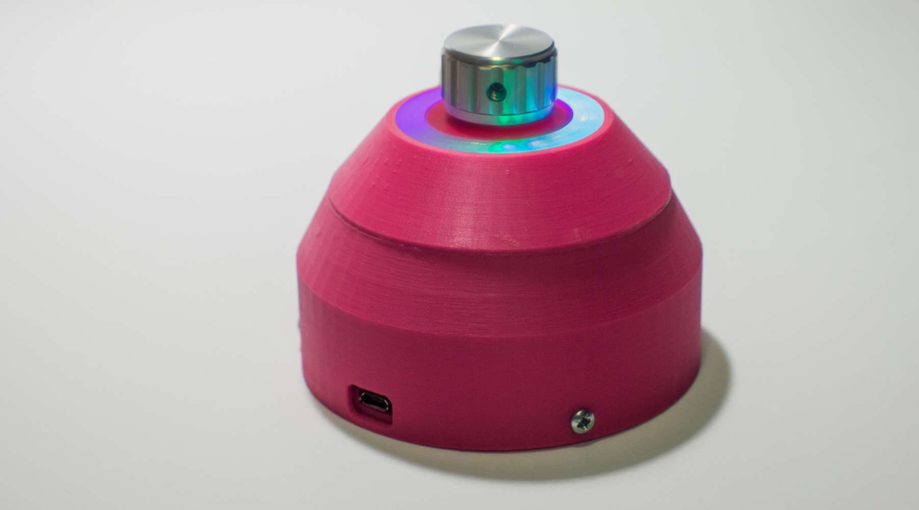
This is the final form. Completely wireless, rechargeable device.
To wake it up you have to tap the knob once. After it wakes up it automatically connects to the first chromecast device, you can control its volume by turning the knob. To change the device tap the knob again. To stop the music playback press and hold the knob until the LEDs turn red.
install esptool and ampy
pip install esptool
pip install adafruit-ampy
erase the flash with esptool
esptool.py --port COM5 erase_flashdownload the micropython firmware
deploy the firmware
esptool.py --port COM5 --baud 460800 write_flash --flash_size=detect 0 esp8266-20170108-v1.8.7.binConfiguring wificonf.py
put the code to the mcu
ampy -p COM5 -b 115200 put     main.py
                boot.py
                encoder.py
                wificonf.py
volume.py| Qty | Value | Footprint | References |
|---|---|---|---|
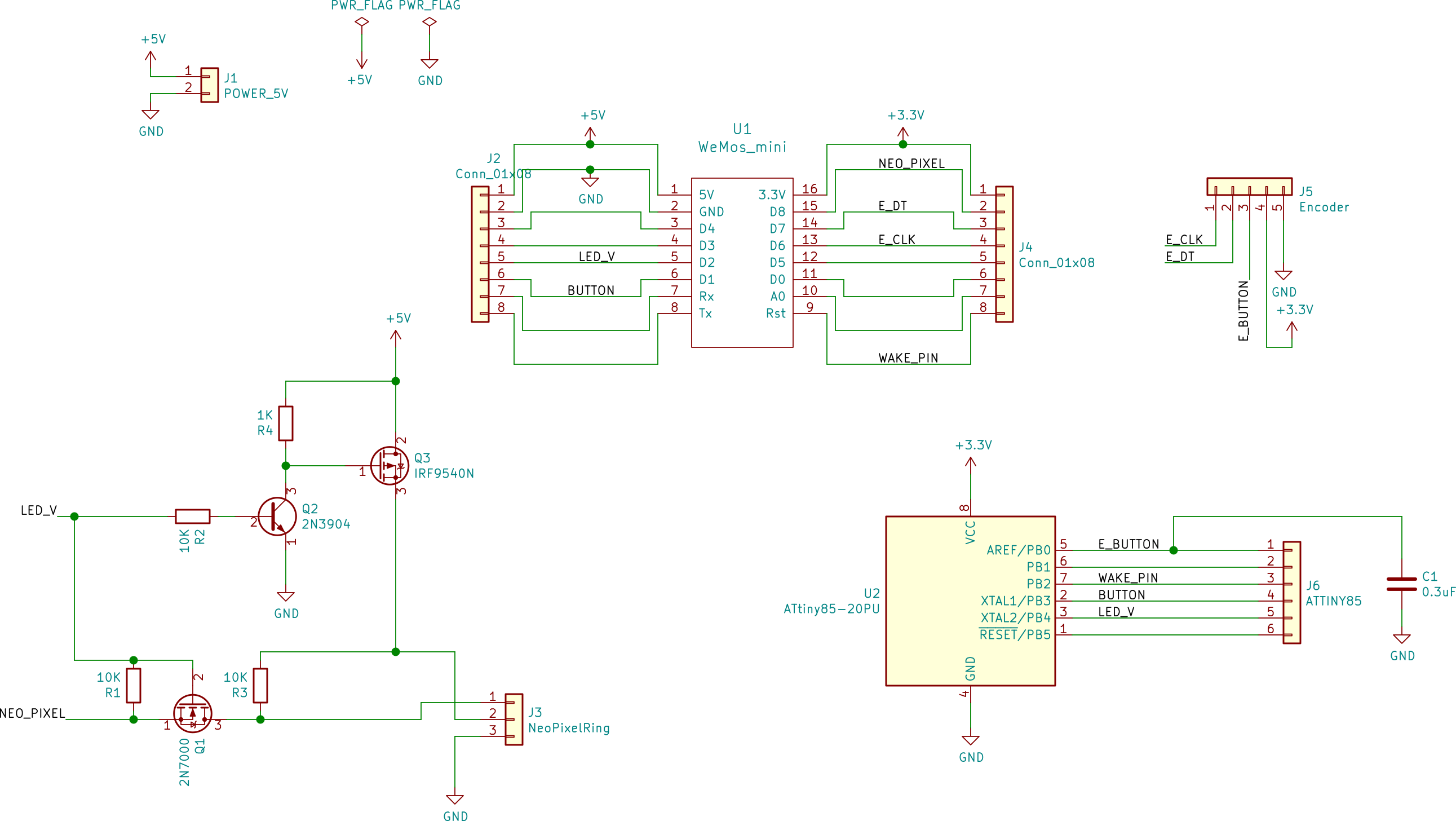
| 3 | 10K | Resistor_THT:R_Axial_DIN0207_L6.3mm_D2.5mm_P10.16mm_Horizontal | R1, R2, R3 |
| 2 | MountingHole:MountingHole_3.2mm_M3_ISO14580_Pad | , | |
| 2 | Conn_01x08 | Connector_PinHeader_2.54mm:PinHeader_1x08_P2.54mm_Vertical | J2, J4 |
| 1 | 0.3uF | Capacitor_THT:C_Disc_D3.8mm_W2.6mm_P2.50mm | C1 |
| 1 | 1K | Resistor_THT:R_Axial_DIN0207_L6.3mm_D2.5mm_P10.16mm_Horizontal | R4 |
| 1 | 2N3904 | Package_TO_SOT_THT:TO-92_Inline | Q2 |
| 1 | 2N7000 | Package_TO_SOT_THT:TO-92_Inline | Q1 |
| 1 | ATTINY85 | Connector_PinHeader_2.54mm:PinHeader_1x06_P2.54mm_Vertical | J6 |
| 1 | ATtiny85-20PU | Package_DIP:DIP-8_W7.62mm_Socket_LongPads | U2 |
| 1 | Encoder | Connector_PinHeader_2.54mm:PinHeader_1x05_P2.54mm_Horizontal | J5 |
| 1 | IRF9540N | Package-TO:TO-220-3_Horizontal_TabDown-132 | Q3 |
| 1 | NeoPixelRing | Connector_PinHeader_2.54mm:PinHeader_1x03_P2.54mm_Horizontal | J3 |
| 1 | POWER_5V | Connector_PinHeader_2.54mm:PinHeader_1x02_P2.54mm_Horizontal | J1 |
| 1 | WeMos_mini | wemos-d1-mini:wemos-d1-mini-connectors-only | U1 |
cnlohr/ethertiny
A firmware-only half-duplex 10Base-T implementation for AVRs


Guiimartinho/routeai
LLM-Powered Electronic Design Automation Platform for PCB Design

rallekralle11/Tinyreflow
Inspired by afterearthltd's reflow plate, but using fewer and simpler components.

aleh/MIDIMonkey
Listens to MIDI messages on one pin and triggers drums on the others


18 parts, built around the ATTINY85-20PU, ATTINY85-15M and IRF9540NS. The full list of its parts is on this page, with links to each part's symbol and footprint where PCBKit's library has them.
From the WebmasterTD/CastVolumeKnob repository on GitHub, at the commit this page was made from: the board is pcb_design/CastVolumeKnob/CastVolumeKnob.kicad_pcb. PCBKit opens the board in the browser, with nothing to install.
Its repository states no licence, so its author keeps all rights: ask WebmasterTD before reusing the design.