
4 layers45 × 41 mm
Osw
Open-Smartwatch/open-smartwatch-gps
Hardware design files for the GPS version of the open-smartwatch
70 parts243GPL-3.0

 rroels/BMA400-breakout
BMA400 Breakout Board
BMA400-breakout is an open-source printed circuit board by rroels, from the rroels/BMA400-breakout repository on GitHub. It is a 2-layer board of 19.8 × 18.7 mm with 8 parts on 8 nets, routed with 49 tracks and 9 vias.
It is built around the BMA400. Its parts include 3 connectors, 2 capacitors and 2 resistors. It belongs with the interfaces and adapters and microcontroller boards boards of this library.
[!WARNING] The information and material (code, designs, files, ...) are provided "AS IS". We make no representation or warranty of any kind, express or implied, regarding the accuracy, adequacy, validity, reliability, availability, or completeness of any information or material. Use this at your own risk.
[!WARNING] At the time of writing this PCB has not even been produced yet, and as such, it has not even been tested yet! Once it has been properly tested, I will confirm that everything works as expected.
This is a breakout board for the Bosch BMA400 acceleration sensor.
https://www.bosch-sensortec.com/products/motion-sensors/accelerometers/bma400/
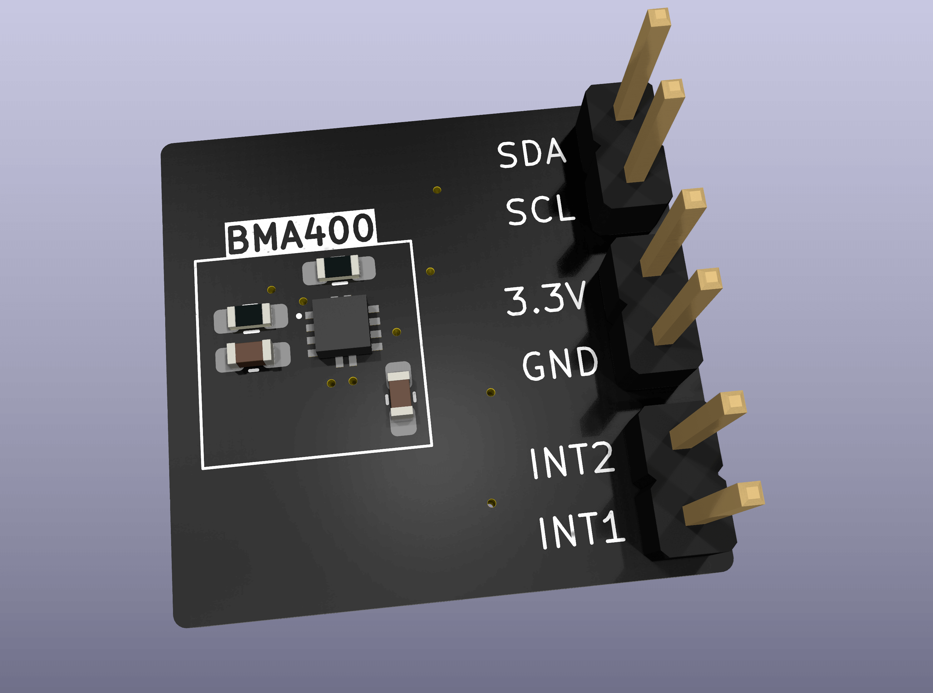
v1.1
v1.0
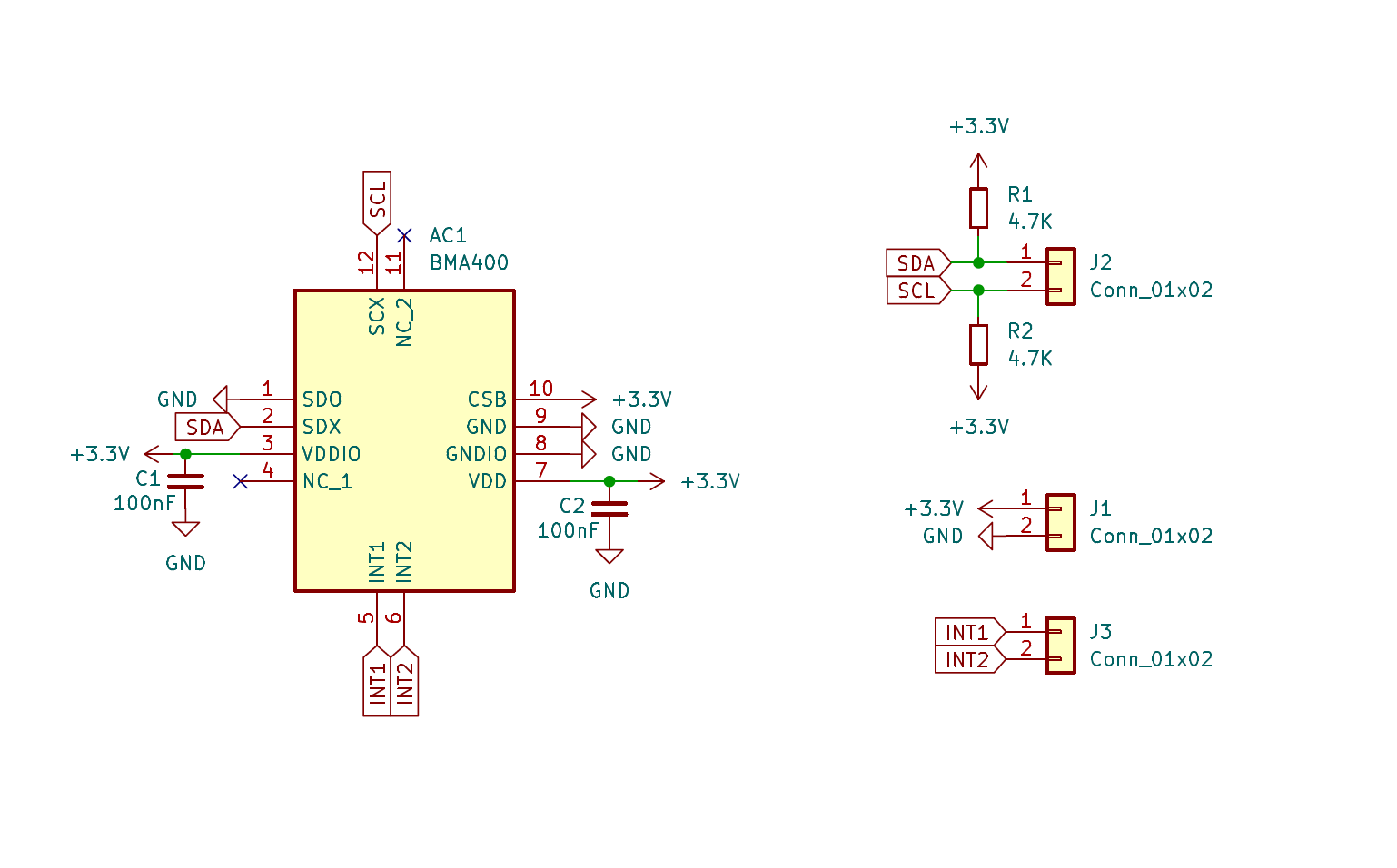
The Gerber file is in this repository (gerbers/BMA400-breakout.zip). Simply upload this file a PCB manufacturer of your choice (JLPCB, PCBWay, ...), and you they will make it for you for as low as $5 for 5 pieces (with the cheapest shipping option, which can take a few weeks).
For JLCPCB, select the order number option where they will replace "JLCJLCJLCJLC" on the board with the actual order number.
[!WARNING] Note that will still have to solder the components onto the PCB yourself!
Everything you need to edit this design in KiCad 8 is included in the repository.
However, this project uses symbols, footprints and 3D models from Component Search Engine. Their license allows us to do pretty much whatever we want with them, except redistributing them. For this reason I can't include them in this repository.
If you would like to edit the design yourself, you will need to download the following component libraries from https://componentsearchengine.com/ (it's free!):
From the downloaded zip files, move the content of the KiCad and 3D subfolders into the project structure, so that the end-result looks like this:
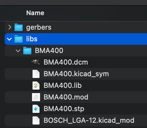
The KiCad project is configured to look for these files in these locations, using relative paths, so no changes to the project itself are required.
| Qty | Value | Footprint | References |
|---|---|---|---|
| 3 | Conn_01x02 | Connector_PinHeader_2.54mm:PinHeader_1x02_P2.54mm_Vertical | J1, J2, J3 |
| 2 | 100nF | Capacitor_SMD:C_0603_1608Metric_Pad1.08x0.95mm_HandSolder | C1, C2 |
| 2 | 4.7K | Resistor_SMD:R_0603_1608Metric_Pad0.98x0.95mm_HandSolder | R1, R2 |
| 1 | BMA400 | BMA400:BOSCH_LGA-12 | AC1 |
Open-Smartwatch/open-smartwatch-gps
Hardware design files for the GPS version of the open-smartwatch


mjculross/Teensy-RV-Leveling-Helper
RV LEveling Helper using Teensy 4.0 + BMA400 Triple Axis Accelerometer Breakout + ILI9341 Color 320x240 TFT Touchscreen display

uw-x/clearbuds-hw
Errata: The design contains some errors that can be addressed in future revisions. The errors do not affect function, but do affect robustness. 1. Add 0.1uF decoupling capacitor to PDM mic (ICS-41350) Vcc. 2.

timohueser/OpenBikeComputer
Open source Bikecomputer with a focus on exploration and adventure.


TUDSSL/FreeBie
To compile FreeBie runtime we used the GNU Arm Embedded Toolchain (9.3.1) and CMake (3.19.1) to build the project. To program the MCU we used the J-Link debug probe with the accompanying J-Link software.

It measures 19.8 × 18.7 mm and has 2 copper layers, 1.6 mm thick.
8 parts, built around the BMA400. The full list of its parts is on this page, with links to each part's symbol and footprint where PCBKit's library has them.
From the rroels/BMA400-breakout repository on GitHub, at the commit this page was made from: the board is kicad/BMA400-breakout.kicad_pcb and its schematic kicad/BMA400-breakout.kicad_sch. PCBKit opens the board in the browser, with nothing to install.
Its repository states no licence, so its author keeps all rights: ask rroels before reusing the design.