

4 layers97 × 94 mm
Main PCB
root670/dance-pad
Dance pad using FSRs and RGB LEDs in an extruded aluminum frame.
20 parts13MIT
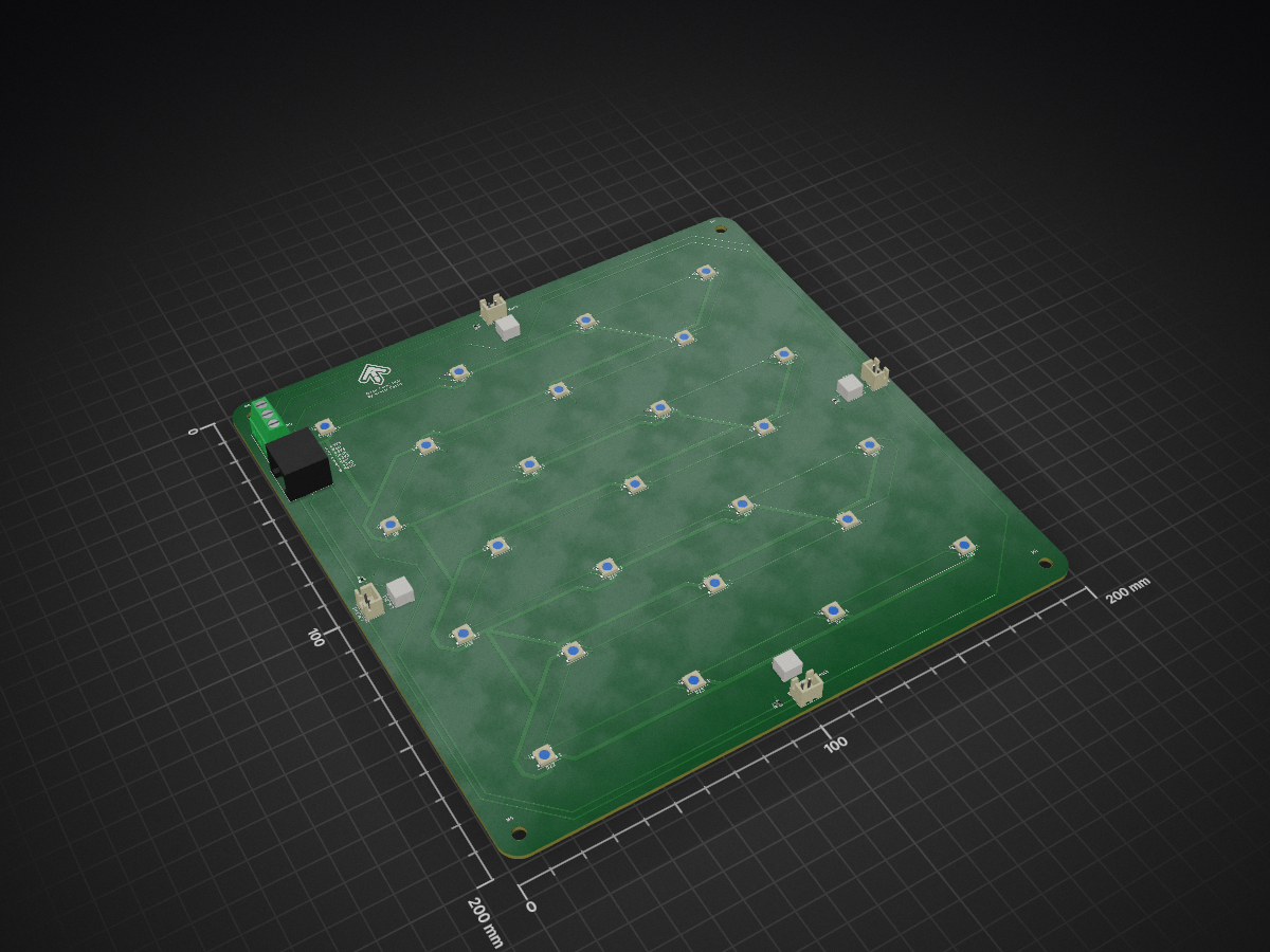
 root670/dance-pad13
Dance pad using FSRs and RGB LEDs in an extruded aluminum frame.
DDR Pad is an open-source printed circuit board by root670, from the root670/dance-pad repository on GitHub, published under the MIT licence. It is a 2-layer board of 200 × 200 mm with 44 parts on 33 nets, routed with 374 tracks and 33 vias.
It is built around the WS2812B and RJ45. Its parts include 25 diodes, 4 resistors and 2 connectors. It belongs with the lEDs and displays boards of this library.
Board placed under each panel. Houses 25 WS2812B V5 RGB LEDs and connects to 4 FSR sensors using JST-XE or JST-ZH connectors. Connects back to the Main PCB using a CAT6 cable for the sensors and cables secured to a screw terminal for the lights.
| Qty | Value | Footprint | References |
|---|---|---|---|
| 25 | WS2812B | LED_SMD:LED_WS2812B_PLCC4_5.0x5.0mm_P3.2mm | D1, D2, D10, D11, D12, D13, D14, D15, D16, D17, D18, D19, D20, D21, D22, D23 +9 |
| 4 | 330 | Resistor_SMD:R_0603_1608Metric | R1, R2, R3, R4 |
| 4 | Conn_01x02 | Connector_JST:JST_ZE_B02B-ZESK-1D_1x02_P1.50mm_Vertical | J_E_ZE1, J_N_ZE1, J_S_ZE1, J_W_ZE1 |
| 4 | Conn_01x02 | Connector_JST:JST_XH_B2B-XH-A_1x02_P2.50mm_Vertical | J_E_XH1, J_N_XH1, J_S_XH1, J_W_XH1 |
| 4 | MountingHole_4.3mm_M4 | MountingHole:MountingHole_4.3mm_M4 | M4, M4, M4, M4 |
| 1 | Conn_01x03 | footprints:1935174 | J9 |
| 1 | LOGO | DDR Pad:DDR Arrow | G*** |
| 1 | RJ45 | RJHSE-5080:AMPHENOL_RJHSE-5080 | J10 |
root670/dance-pad
Dance pad using FSRs and RGB LEDs in an extruded aluminum frame.


UtilitechAS/amsreader-firmware
ESP8266 and ESP32 compatible firmware to read, interpret and publish data to MQTT from smart electrical meters, both DLMS and DSMR is supported

travisgoodspeed/goodfet
An embedded bus adapter for various microcontrollers and radios.


nv1t/standing-desk-interceptor
I wanted to intercept the communication between my Flexispot standing desk buttons. This is the progress on the project


Severson-Group/AMDC-Hardware
Circuit board designs for controlling advanced motor systems
It measures 200 × 200 mm and has 2 copper layers, 1.6 mm thick.
44 parts, built around the WS2812B and RJ45. The full list of its parts is on this page, with links to each part's symbol and footprint where PCBKit's library has them.
From the root670/dance-pad repository on GitHub, at the commit this page was made from: the board is Arrow PCB/DDR Pad.kicad_pcb. PCBKit opens the board in the browser, with nothing to install.
Its repository publishes it under the MIT licence: you may reuse it on that licence's terms (keep the author's notice, and for a copyleft licence share your changes alike).