
2 layers33.7 × 97.8 mm
HAN ESP TSS721
UtilitechAS/amsreader-firmware
ESP8266 and ESP32 compatible firmware to read, interpret and publish data to MQTT from smart electrical meters, both DLMS and DSMR is supported
29 parts470

 olvint/CM4-NAS-MiniPCIE51
Raspberry Pi CM4 based NAS solution board
CM4 2 Backup is an open-source printed circuit board by olvint, from the olvint/CM4-NAS-MiniPCIE repository on GitHub. It is a 4-layer board of 90 × 75 mm with 21 parts on 172 nets, routed with 1,041 tracks and 132 vias.
It is built around the RJ45. Its parts include 16 connectors, 2 fuses, 1 capacitor and 1 resistor. It belongs with the computers and single-board computers boards and the Raspberry Pi (Linux) boards of this library.
Rapberry PI compute module 4 NAS PCB for using JLCPCB.com. (pre-test version)
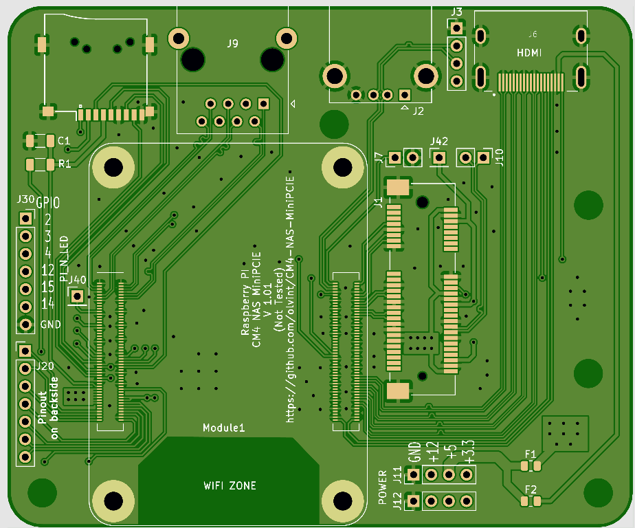
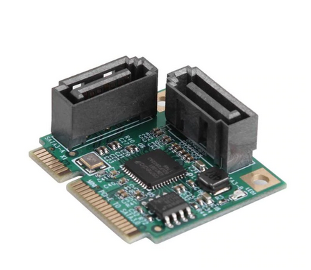
Main purpose of design is to make NAS with more reliable SATA connection comparing to USB-to-SATA converters. SATA controllers can be connected through MiniPCIe slot. There are variety of cards in market, mainly my intend was to use this for 2 SATA (see picture below). This is half size card. Cards for 4 SATA with RAID controller also can be connected.
Design is made using nighly version of KiCAD 5.99.0 Please study Raspberry PI CM4 datasheet
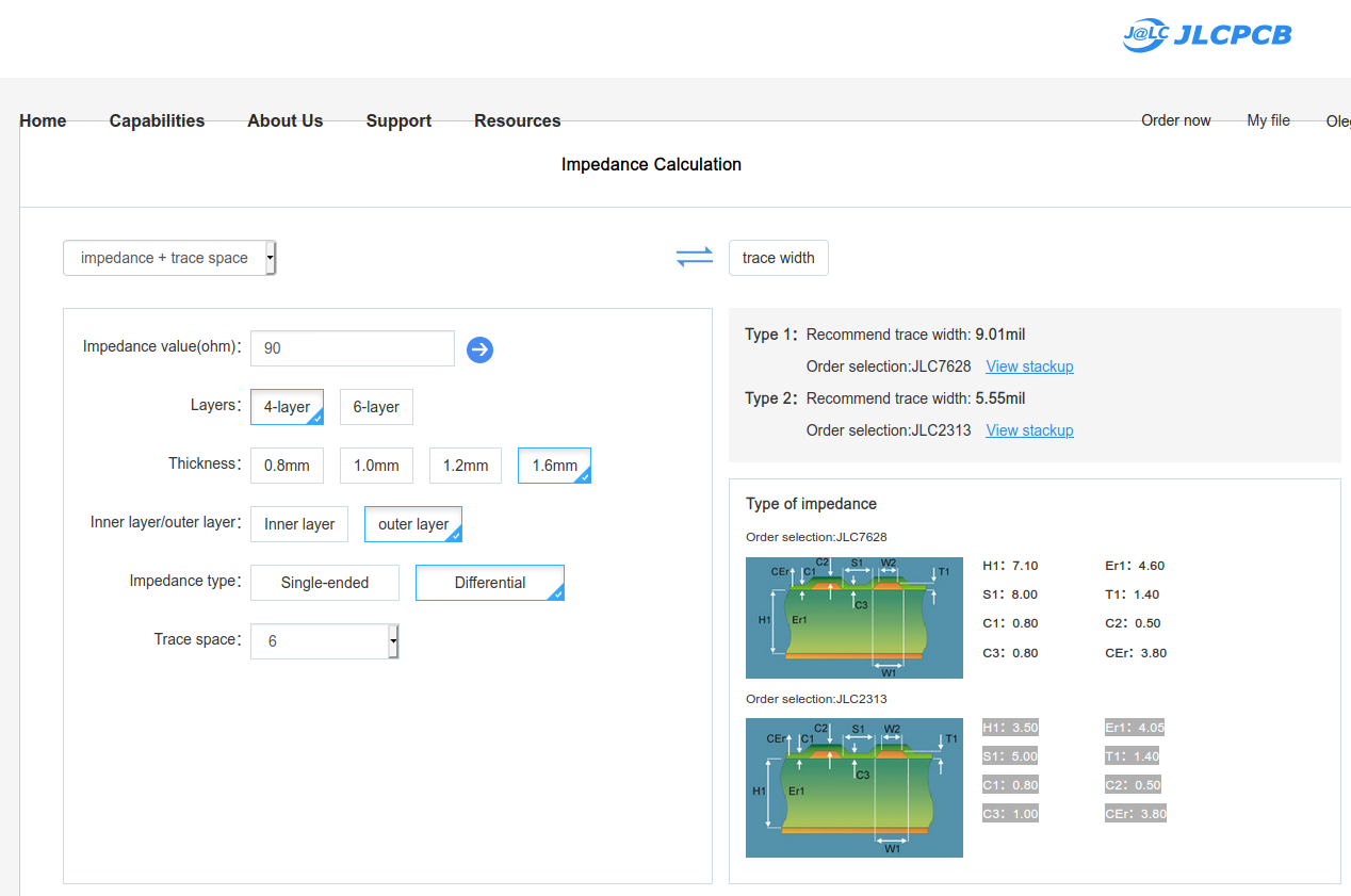
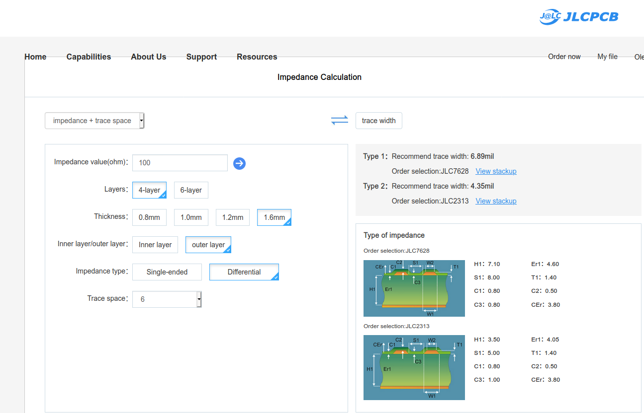
PCB was designed by a newcomer. All steps made are listed below. This section is very important and risky. Mistakes can be made. 90 R and 100R impedance differential lines are used.Calculations of differential lines are made using JLCPCB internal calculator
Results of calculation - 90R and 100R
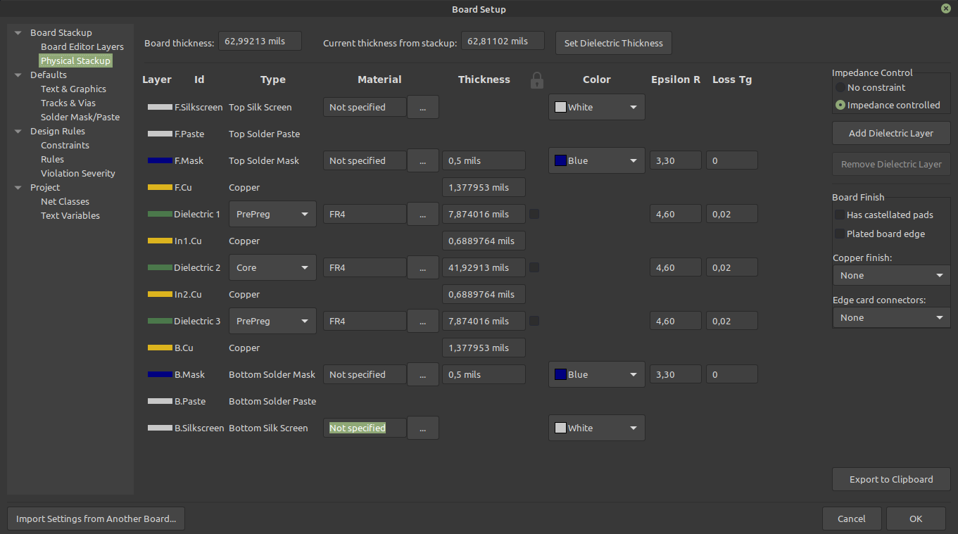
Those results put in KiCAD.

JLC7628 Stackup used all settings transfered to KiCAD stackup
All vias minimal diameter is 0.45 as price will be much higher for VIAs of less size.
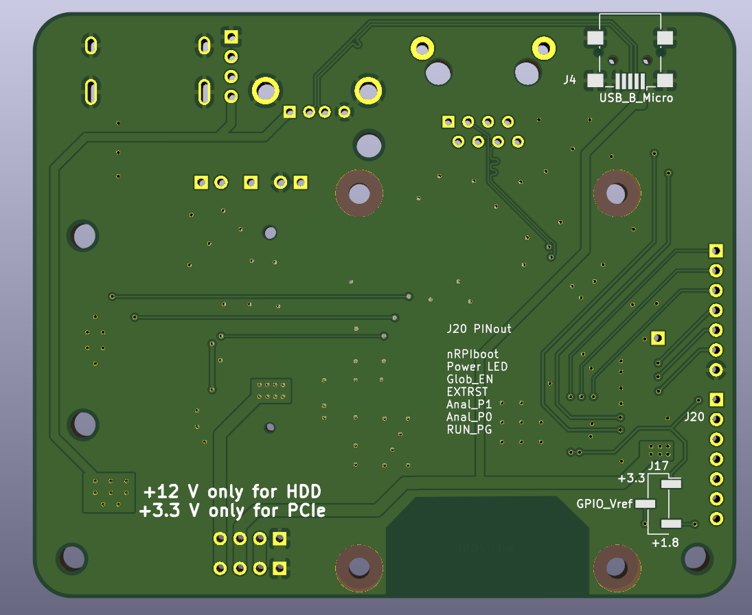
All sockets footprints selected to be most common. In standard library of KiCAD I did not found suitable MicroSD socket. And ofcource footprint of CM4 is also taken from Raspberry PI CM4 IO borad. All external footprints are in folder LIBS. I wanted to install all sockets on one side of the board and there was not much space. MicroUSB socket I put on other side of the board below MicroSD socket.
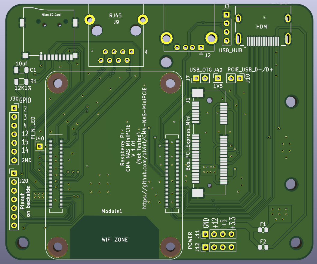
There are 2 connectors with 4 pins (GND, +12V, +5V, +3.3V) Connectors can be used for powering board and soldering cable for powering HDDs.
Initial CM4 IO Borad has more copmplicated power system with different ICs for protecting not only from short circuit but, under voltage, overload etc.
Left side of board has GPIO connector and small connector for selecting level of GPIO (GPIO_Vref)
There is a connector with following signals
GBR files are prepared in FAB folder. Also archive prepared FAB_JLCPCB.zip for making order. Please note that you need to turn on option Impedance and select JLCPCB7628 stackup
Front
Back
Update 28.12.2020 - Rerouted some tracks. Moved MicroUSB below MicroSD. Update 02.01.2021 - Rerouted a lot of tracks. Added beauty.
| Qty | Value | Footprint | References |
|---|---|---|---|
| 2 | Polyfuse | Resistor_SMD:R_0805_2012Metric | F1, F2 |
| 1 | 10uf | Capacitor_SMD:C_1206_3216Metric | C1 |
| 1 | 12K1% | Resistor_SMD:R_1206_3216Metric | R1 |
| 1 | 1V5 | Connector_PinHeader_2.54mm:PinHeader_1x01_P2.54mm_Vertical | J42 |
| 1 | Bus_PCI_Express_Mini | Connector_PCBEdge:BUS_PCI_Express_Mini_Half | J1 |
| 1 | ComputeModule4-CM4 | CM4IO:Raspberry-Pi-4-Compute-Module | Module1 |
| 1 | Conn_01x07_Female | Connector_PinSocket_2.54mm:PinSocket_1x07_P2.54mm_Vertical | J30 |
| 1 | Controll Connector | Connector_PinHeader_2.54mm:PinHeader_1x07_P2.54mm_Vertical | J20 |
| 1 | GPIO_V | Connector_PinHeader_2.54mm:PinHeader_1x03_P2.54mm_Vertical_SMD_Pin1Right | J17 |
| 1 | HDMI_A_1.4 | CM4IO:EDAC 690-019-298-412 | J6 |
| 1 | Micro_SD_Card | SD:Conn_uSDcard | J5 |
| 1 | N_LED | Connector_PinHeader_2.54mm:PinHeader_1x01_P2.54mm_Vertical | J40 |
| 1 | PCIE_USB_D-/D+ | Connector_PinHeader_2.54mm:PinHeader_1x02_P2.54mm_Vertical | J10 |
| 1 | RJ45 | Connector_RJ:RJ45_Ninigi_GE | J9 |
| 1 | USB_A | Connector_USB:USB_A_CONNFLY_DS1095-WNR0 | J2 |
| 1 | USB_B_Micro | Connector_USB:USB_Mini-B_Lumberg_2486_01_Horizontal | J4 |
| 1 | USB_HUB | Connector_PinHeader_2.54mm:PinHeader_1x04_P2.54mm_Vertical | J3 |
| 1 | USB_OTG | Connector_PinHeader_2.54mm:PinHeader_1x02_P2.54mm_Vertical | J7 |
| 1 | V_IN1 | Connector_PinHeader_2.54mm:PinHeader_1x04_P2.54mm_Vertical | J11 |
| 1 | V_IN2 | Connector_PinHeader_2.54mm:PinHeader_1x04_P2.54mm_Vertical | J12 |
UtilitechAS/amsreader-firmware
ESP8266 and ESP32 compatible firmware to read, interpret and publish data to MQTT from smart electrical meters, both DLMS and DSMR is supported

travisgoodspeed/goodfet
An embedded bus adapter for various microcontrollers and radios.


nv1t/standing-desk-interceptor
I wanted to intercept the communication between my Flexispot standing desk buttons. This is the progress on the project

Severson-Group/AMDC-Hardware
Circuit board designs for controlling advanced motor systems

mfkiwl/KiwiSDR_PCB
KiCAD PCB files for KiwiSDR project including active antenna and bias tee

GBert/railroad
git clone https://github.com/arendst/Tasmota.git cd Tasmota git tag pio run
It measures 90 × 75 mm and has 4 copper layers, 1.6 mm thick.
21 parts, built around the RJ45. The full list of its parts is on this page, with links to each part's symbol and footprint where PCBKit's library has them.
From the olvint/CM4-NAS-MiniPCIE repository on GitHub, at the commit this page was made from: the board is CM4_2_Backup.kicad_pcb and its schematic CM4_2.kicad_sch. PCBKit opens the board in the browser, with nothing to install.
Its repository states no licence, so its author keeps all rights: ask olvint before reusing the design.