
2 layers200 × 70 mm
FRL RFiD Box
FREILab/easyVerwaltungHardware
Hardware und Firmware für alle Geräte im Bezug zu easyVerwaltung
65 parts2

Circuit board designs for controlling advanced motor systems
Aei is an open-source printed circuit board by Severson-Group, from the Severson-Group/AMDC-Hardware repository on GitHub. It is a 4-layer board of 73.9 × 84.5 mm with 54 parts on 33 nets, routed with 287 tracks and 25 vias.
It is built around the RS6-2405S, RS6-2415D and INA2143U, with the 3362P-1-103LF and RJ45 among its other parts. Its parts include 13 capacitors, 4 resistors, 4 connectors, 3 ICs and 3 diodes. It belongs with the fPGA and programmable logic boards of this library.


The Advanced Motor Drive Controller (AMDC) is an open-source project from the Severson Research Group at UW-Madison, affiliated with Wisconsin Electric Machines and Power Electronics Consortium (WEMPEC).
Learn more at docs.amdc.dev.
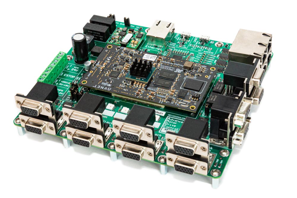
AMDC-Hardware is a collection of circuit board designs which are used to control advanced motor systems. The hardware design is open-source, modular, and research-oriented.
The flagship circuit board is the main AMDC (see latest design here) which is a carrier board for the PicoZed System-on-Module. The PicoZed is a module itself which contains the core requirements for the Xilinx Zynq-7000 System-on-Chip. The Xilinx Zynq-7000 SoC is a powerful processor with dual-core DSPs and a tightly integrated FPGA.
Extensive firmware support is provided in the AMDC-Firmware repo which targets this architecture.
The altium directory contains all files pertaining to schematics / board design in Altium Designer. These files should be the latest working copy of the project.
The REVyyyymmdd* directories represent snapshots of the project that were used to produce a physical PCB. These directories contain the Gerber, Drill (Excellon format), Bill of Materials (CSV), and Schematic (PDF) files.
REV indicates a revision of design for manufacturingyyyymmdd indicates the date on which design was frozen* (letter) indicates which revision in sequence (A - first, B - second, etc.)Numerous accessory circuit boards are designed to work with the AMDC (e.g., DAC, TestBoard, CAN expansion, I/O expansion).
These are located in the /Accessories/ subfolder. Each accessory board follows the same repo set-up conventions as desribed above for the main AMDC.
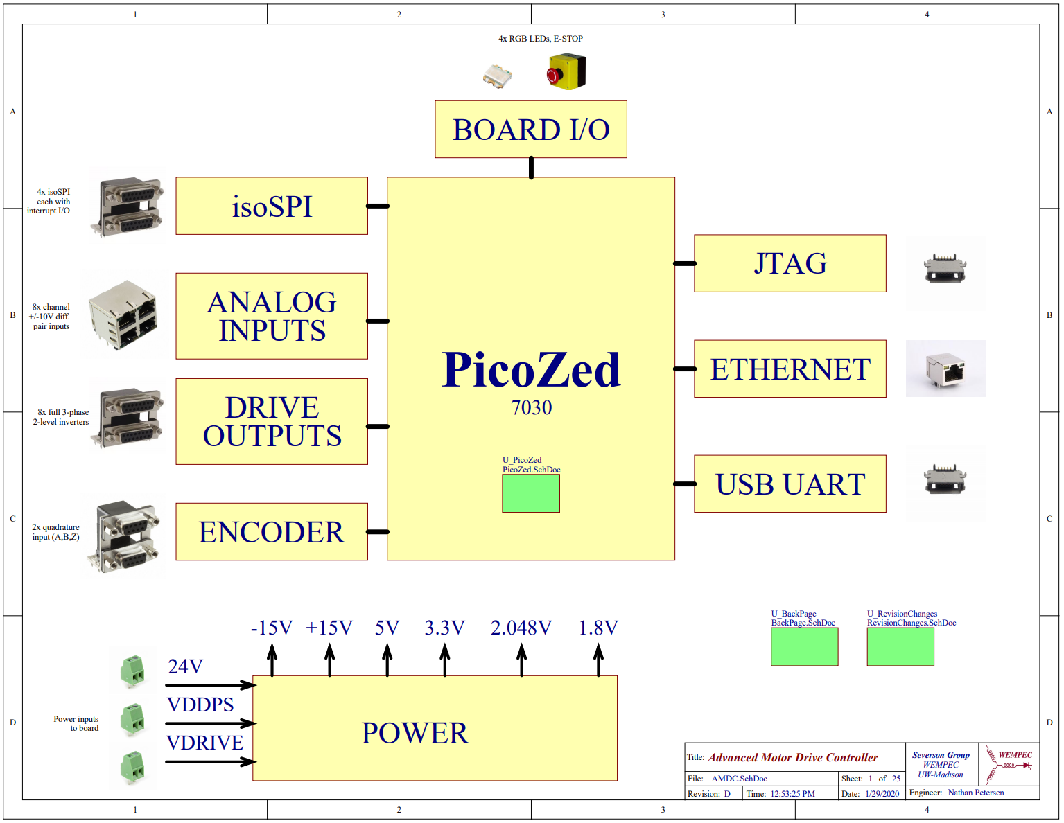
The AMDC is designed for research environments where flexible and plentiful I/O are required.
The provided interfaces include:
The AMDC-Hardware project is open-source -- contributors are welcome!
The REVxxxx/ output folder contains the compiled design files needed to order hardware:
docs/ folder for any imformation about the board designREVxxxx/gerbers/ folder and the specs provided in the README.md fileNote: all board designs are created using Altium Designer -- a license is required to design boards for the AMDC-Hardware project.
The altium/ subfolder contains the latest design files for the board.
Detailed documentation about the hardware is available online at: docs.amdc.dev/hardware.
The documentation explains the design narrative and process, design choices, requirements, relevant equations and diagrams, etc.
This project originated as Nathan Petersen's Independent Study project during Spring 2018, advised by Prof. Eric Severson. It is now actively maintained by the Severson Research Group. Open source firmware is available on GitHub in the AMDC-Firmware repository.
| Qty | Value | Footprint | References |
|---|---|---|---|
| 18 | TestPoint | TestPoint:TestPoint_Keystone_5000-5004_Miniature | TP1, TP2, TP3, TP4, TP5, TP6, TP10, TP11, TP12, TP13, TP14, TP15, TP16, TP17, TP18, TP19 +2 |
| 6 | 1uF | Capacitor_SMD:C_0603_1608Metric_Pad1.08x0.95mm_HandSolder | C5, C6, C10, C11, C12, C13 |
| 4 | MountingHole | MountingHole:MountingHole_3.2mm_M3_DIN965_Pad_TopBottom | H1, H2, H3, H4 |
| 3 | 10uF | Capacitor_SMD:C_0805_2012Metric_Pad1.18x1.45mm_HandSolder | C3, C4, C7 |
| 3 | 3k | Resistor_SMD:R_0603_1608Metric_Pad0.98x0.95mm_HandSolder | R3, R4, R5 |
| 3 | 6.8uF | Capacitor_SMD:C_1206_3216Metric_Pad1.33x1.80mm_HandSolder | C1, C2, C9 |
| 2 | INA2143U | INA2143U:D14 | U1, U2 |
| 2 | RED | LED_SMD:LED_0603_1608Metric_Pad1.05x0.95mm_HandSolder | LED1, LED3 |
| 2 | Screw_Terminal_01x06 | TerminalBlock_Phoenix:TerminalBlock_Phoenix_MKDS-1,5-6_1x06_P5.00mm_Horizontal | J1, J3 |
| 1 | 10 uF | Capacitor_SMD:C_0603_1608Metric_Pad1.08x0.95mm_HandSolder | C8 |
| 1 | 1935161 | TerminalBlock_Phoenix:TerminalBlock_Phoenix_MKDS-1,5-2_1x02_P5.00mm_Horizontal | J2 |
| 1 | 3362P-1-103LF | Varistor:TRIM_3362P-1-103LF | VR1 |
| 1 | 70R | Resistor_SMD:R_1206_3216Metric_Pad1.30x1.75mm_HandSolder | R2 |
| 1 | LOGO | Motors:elev_logo | G*** |
| 1 | LT1764EQ-1.5-PBF | LTI1764EQ:DDPAK-5_Q_LIT | U3 |
| 1 | RJ45 | Connector_RJ:RJ45_Amphenol_RJHSE5380 | J4 |
| 1 | RS6-2405S | RS6_2405S:CONV_RS6-2405S | PS1 |
| 1 | RS6-2415D | RS6_2415D:CONV_RS6-2415D | PS2 |
| 1 | WE-SL5_HC | WE-SL5_HC:WE-SL5_HC | L1 |
| 1 | YELLOW | LED_SMD:LED_0603_1608Metric_Pad1.05x0.95mm_HandSolder | LED2 |
FREILab/easyVerwaltungHardware
Hardware und Firmware für alle Geräte im Bezug zu easyVerwaltung

xpix/XMOTO_TINYAVR
This code is designed for a motor controller and has merged the PID code of Josh Kopel with the code of the Makerbot servo-controller board. This code can be used on some boards by changing some values.


slemanz/chronolog
STM32-based temperature data logger with RTC, NOR flash storage, LCD and Wi-Fi. Hardware and firmware.


justharihere/PWM_Modulator
This is an experimental PWM Modulator I developed while experimenting with NE555 timer ICs, datasheets, and learning PCB fab.


It measures 73.9 × 84.5 mm and has 4 copper layers, 1.68 mm thick.
54 parts, built around the RS6-2405S, RS6-2415D, INA2143U and 3362P-1-103LF. The full list of its parts is on this page, with links to each part's symbol and footprint where PCBKit's library has them.
From the Severson-Group/AMDC-Hardware repository on GitHub, at the commit this page was made from: the board is Accessories/AnalogEncoderInterface/kicad/aei.kicad_pcb and its schematic Accessories/AnalogEncoderInterface/kicad/aei.kicad_sch. PCBKit opens the board in the browser, with nothing to install.
Its repository states no licence, so its author keeps all rights: ask Severson-Group before reusing the design.