2 layers90 × 98.5 mm
IO Board
FREILab/easyVerwaltungHardware
Hardware und Firmware für alle Geräte im Bezug zu easyVerwaltung
77 parts2
 FREILab/easyVerwaltungHardware2
Hardware und Firmware für alle Geräte im Bezug zu easyVerwaltung
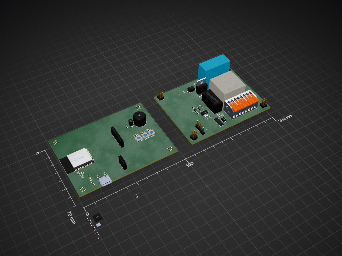
FRL RFiD Box is an open-source printed circuit board by FREILab, from the FREILab/easyVerwaltungHardware repository on GitHub. It is a 2-layer board of 200 × 70 mm with 65 parts on 143 nets, routed with 130 tracks and 0 vias.
It is built around the ESP32-S3-WROOM-1-N8, RAC05-24SK and RS6-2405S, with the AMS1117-3.3, WS2812 and BC547 among its other parts. Its parts include 20 capacitors, 14 connectors, 10 resistors, 8 diodes and 5 ICs. It belongs with the radio and wireless boards and the ESP32 boards of this library.


Firmware und Dokumentation für die easyVerwaltung-Hardware des FREILab. Das System steuert Maschinenzugang, Nutzungsprotokollierung und Sicherheit via RFID-Authentifizierung gegen das easyVerwaltung-Backend.
| Projekt | Hardware | API | Status |
|---|---|---|---|
| RFID_BOX_legacy | ESP32 Dev1 | Legacy | Stabil — v1.0.0 |
| RFID_BOX_easyVerwaltung | ESP32 Dev1 | easyVerwaltung | Getestet — Server noch nicht in Production |
| Projekt | Hardware | API | Status |
|---|---|---|---|
| DOOR_legacy | Arduino UNO R4 WiFi | Legacy | Scheduled for Deletion |
| DOOR_legacy_ESPArdu | RobotDyn UNO+WiFi R3 (ATmega328P + ESP8266) | Legacy | Stabil — v1.0.0 |
| DOOR_easyVerwaltung | Arduino UNO R4 WiFi | easyVerwaltung | In Entwicklung |
| Projekt | Hardware | API | Status |
|---|---|---|---|
| LASERSAUR_HMI_legacy | Arduino Mega + Ethernet-Shield | Legacy | Stabil (nicht mit neuem Server getestet) — wird durch ESPArdu ersetzt |
| LASERSAUR_HMI_ESPArdu | Mega2560 WiFi R3 (ATmega2560 + ESP8266) | Legacy | Implementiert, noch nicht getestet |
| LASERSAUR_HMI_easyVerwaltung | Arduino Giga R1 | easyVerwaltung | In Entwicklung |
| Projekt | Hardware | API | Status |
|---|---|---|---|
| MachineNode_legacy | ESP32-S3-WROOM-1-N16R8 | Legacy | Stabil |
| MachineNode_easyVerwaltung | ESP32-S3-WROOM-1-N16R8 | easyVerwaltung | Geplant |
firmware/
  projects/          # Firmware-Targets (je ein PlatformIO-Projekt)
  shared/
    easyAPI/         # Gemeinsame Backend-Kommunikation (HTTP/JSON)
Jedes Projekt in projects/ enthält eine eigene README.md mit Hardware-Details, DIP-Belegung, Flash-Anleitung und Debugging-Hinweisen.
pip install platformio)Jedes Projekt benötigt eine platformio.secrets.ini (nicht in Git). Vorlage liegt als .example-Datei bei:
cp platformio.secrets.ini.example platformio.secrets.ini
# Datei befüllen, dann:
pio run
Details zu den Feldern stehen in der jeweiligen Projekt-README.
| Qty | Value | Footprint | References |
|---|---|---|---|
| 8 | Conn_02x02_Odd_Even | Connector_PinHeader_2.54mm:PinHeader_2x02_P2.54mm_Vertical | J7, J8, J11, J12, J13, J14, J15, J16 |
| 5 | 100n | Capacitor_SMD:C_0603_1608Metric | C14, C17, C18, C20, C21 |
| 5 | 10u | Capacitor_SMD:C_0603_1608Metric | C3, C4, C9, C16, C19 |
| 3 | 0.1uF | Capacitor_SMD:C_0603_1608Metric | C10, C11, C12 |
| 3 | 10k | Resistor_SMD:R_0603_1608Metric | R1, R2, R10 |
| 3 | WS2812 | LED_SMD:LED_WS2812_PLCC6_5.0x5.0mm_P1.6mm | D2, D3, D4 |
| 2 | 1u | Capacitor_SMD:C_0603_1608Metric | C7, C15 |
| 2 | 22p | Capacitor_SMD:C_0603_1608Metric | C23, C24 |
| 2 | 2k2 | Resistor_SMD:R_0603_1608Metric | R8, R9 |
| 2 | 5,1k | Resistor_SMD:R_0603_1608Metric | R5, R6 |
| 2 | Conn_01x05 | Connector_PinHeader_2.54mm:PinHeader_1x05_P2.54mm_Vertical | J9, J10 |
| 1 | 0.1u | Capacitor_SMD:C_0402_1005Metric | C8 |
| 1 | 1N4007 | Diode_THT:D_DO-41_SOD81_P10.16mm_Horizontal | D1 |
| 1 | 1k | Resistor_SMD:R_0603_1608Metric | R4 |
| 1 | 200mA T | Fuse:Fuse_Schurter_UMZ250 | F1 |
| 1 | 220 | Resistor_SMD:R_0603_1608Metric | R3 |
| 1 | 22k | Resistor_SMD:R_0603_1608Metric | R7 |
| 1 | 22u Tantal or Elko | Capacitor_SMD:C_0603_1608Metric | C13 |
| 1 | 27.12MHz | PCM_SparkFun-Clock:Crystal_SMD_3.2x2.5mm | Y1 |
| 1 | 4,7u | Capacitor_SMD:C_0603_1608Metric | C22 |
| 1 | AMS1117-3.3 | Package_TO_SOT_SMD:SOT-223-3_TabPin2 | U6 |
| 1 | BC547 | Package_TO_SOT_THT:TO-92_Inline | Q2 |
| 1 | DMG2305UX | Package_TO_SOT_SMD:SOT-23 | Q3 |
| 1 | ESD9B3.3ST5G | Diode_SMD:D_SOD-923 | D8 |
| 1 | ESP32-S3-WROOM-1 | RF_Module:ESP32-S3-WROOM-1 | U4 |
| 1 | FINDER-41.52.9.024.4311 | Relay_THT:Relay_DPDT_Finder_40.52 | K1 |
| 1 | I2C_OLED | Connector_PinSocket_2.54mm:PinSocket_1x04_P2.54mm_Vertical | J1 |
| 1 | IRLZ44N | Package_TO_SOT_THT:TO-220-3_Vertical | Q1 |
| 1 | LED G | LED_SMD:LED_0603_1608Metric | D7 |
| 1 | MBR120VLSF | Diode_SMD:D_SOD-123F | D5 |
| 1 | PC817 | Package_DIP:DIP-4_W7.62mm | U5 |
| 1 | PN5321A3HN_C1xx | Package_DFN_QFN:HVQFN-40-1EP_6x6mm_P0.5mm_EP4.1x4.1mm | U3 |
| 1 | RAC05-24SK | Converter_ACDC:Converter_ACDC_RECOM_RAC05-xxSK_THT | U1 |
| 1 | RS6-2405S | MOD-DC_DC_Converters:CONV_RS6-2405S | PS1 |
| 1 | SMAJ36CA | Diode_SMD:D_SMA | D6 |
| 1 | SPI_NFC | Connector_PinSocket_2.54mm:PinSocket_1x08_P2.54mm_Vertical | J2 |
| 1 | TMB12A05 | Buzzer_Beeper:Buzzer_12x9.5RM7.6 | BZ1 |
| 1 | USB_C_Receptacle | PCM_SparkFun-Connector:USB-C_16 | J5 |
| 1 | WAGO (230V + 24V) | TerminalBlock_WAGO:TerminalBlock_WAGO_2601-1108_1x08_P3.50mm_Horizontal | J3 |
FREILab/easyVerwaltungHardware
Hardware und Firmware für alle Geräte im Bezug zu easyVerwaltung

Severson-Group/AMDC-Hardware
Circuit board designs for controlling advanced motor systems

devbotas/pcb-voron-pmu
Power management unit for my Voron 2.4 printer to handle blackouts.


jguillen-lab/BFS9000
Custom split ergonomic keyboard PCB based on Sofle Pico (RP2040/Pico). Adds detachable breakaway function row and lateral key packs, SK6803MINI-E per-key RGB, rear underglow (6 per half + 4 per pack), resistor-based…


lapalmaelettronica/Progetti
Una lista dei progetti che ho pubblicato su instagram, potete trovarci pcb, codici, schemo elettrici e stampe 3d!

embeddedci-com/benchpod
An open hardware bench tool that plugs into your CI: sensor sim, CAN, analog I/O, power control, and a Python SDK with pytest integration

EdgeCoil/wiegand-bridge
ESP32-S3 Wiegand reader bridge for Home Assistant: 4-layer board, BOM and ESPHome firmware.
It measures 200 × 70 mm and has 2 copper layers, 1.6 mm thick.
65 parts, built around the ESP32-S3-WROOM-1-N8, RAC05-24SK, RS6-2405S and AMS1117-3.3. The full list of its parts is on this page, with links to each part's symbol and footprint where PCBKit's library has them.
From the FREILab/easyVerwaltungHardware repository on GitHub, at the commit this page was made from: the board is hardware/projects/MicBac/PROJ-FRL-RIFD_Box/Electro/FRL-RFiD_Box/FRL-RFiD_Box.kicad_pcb and its schematic hardware/projects/MicBac/PROJ-FRL-RIFD_Box/Electro/FRL-RFiD_Box/FRL-RFiD_Box.kicad_sch. PCBKit opens the board in the browser, with nothing to install.
Its repository states no licence, so its author keeps all rights: ask FREILab before reusing the design.