
2 layers42.8 × 86.2 mm
PowerTiger
codetiger/PowerTiger
Home power monitoring system - Monitoring energy consumption with better granularity
55 parts19MIT

 RolandThsive/Thermometer
Part of the AQI Board Project by RolandThsive
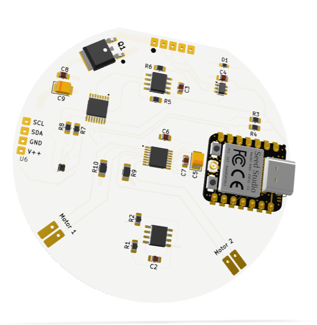
TheMainBoard is an open-source printed circuit board by RolandThsive, from the RolandThsive/Thermometer repository on GitHub. It is a 2-layer board of 29.3 × 68.9 mm with 31 parts on 39 nets, routed with 390 tracks and 176 vias.
It is built around the DRV8833PWP, PCA9546APWRE4 and SHT40-AD1B-R3, with the USBLC6-2SC6 among its other parts. Its parts include 11 ICs, 10 resistors, 8 capacitors, 1 diode and 1 transistor. It belongs with the ESP32 and RISC-V boards of this library.


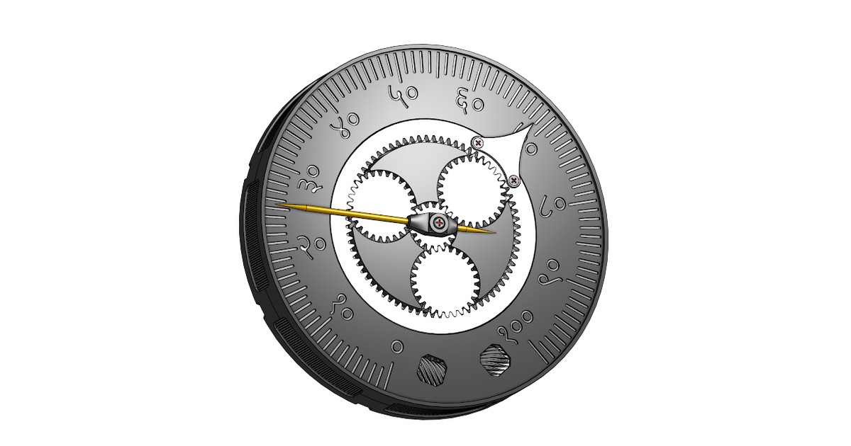








This repository is a part of the AQI Board project by @RolandThsive — a wall of analog-style instruments (hygrometer, thermometer, AQI meter and VOC meter) that are as much a showpiece as they are useful.
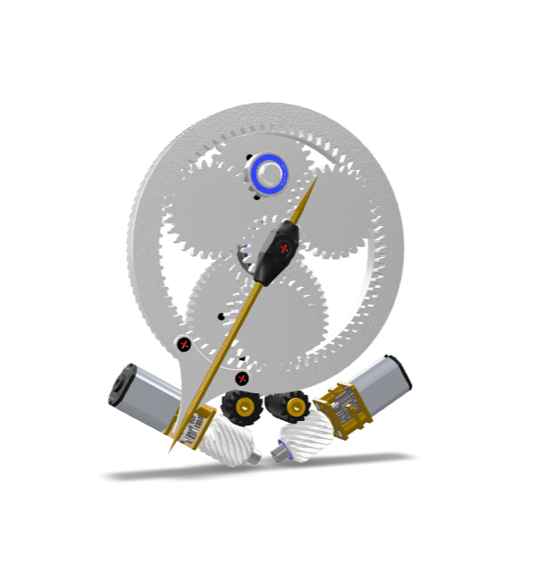
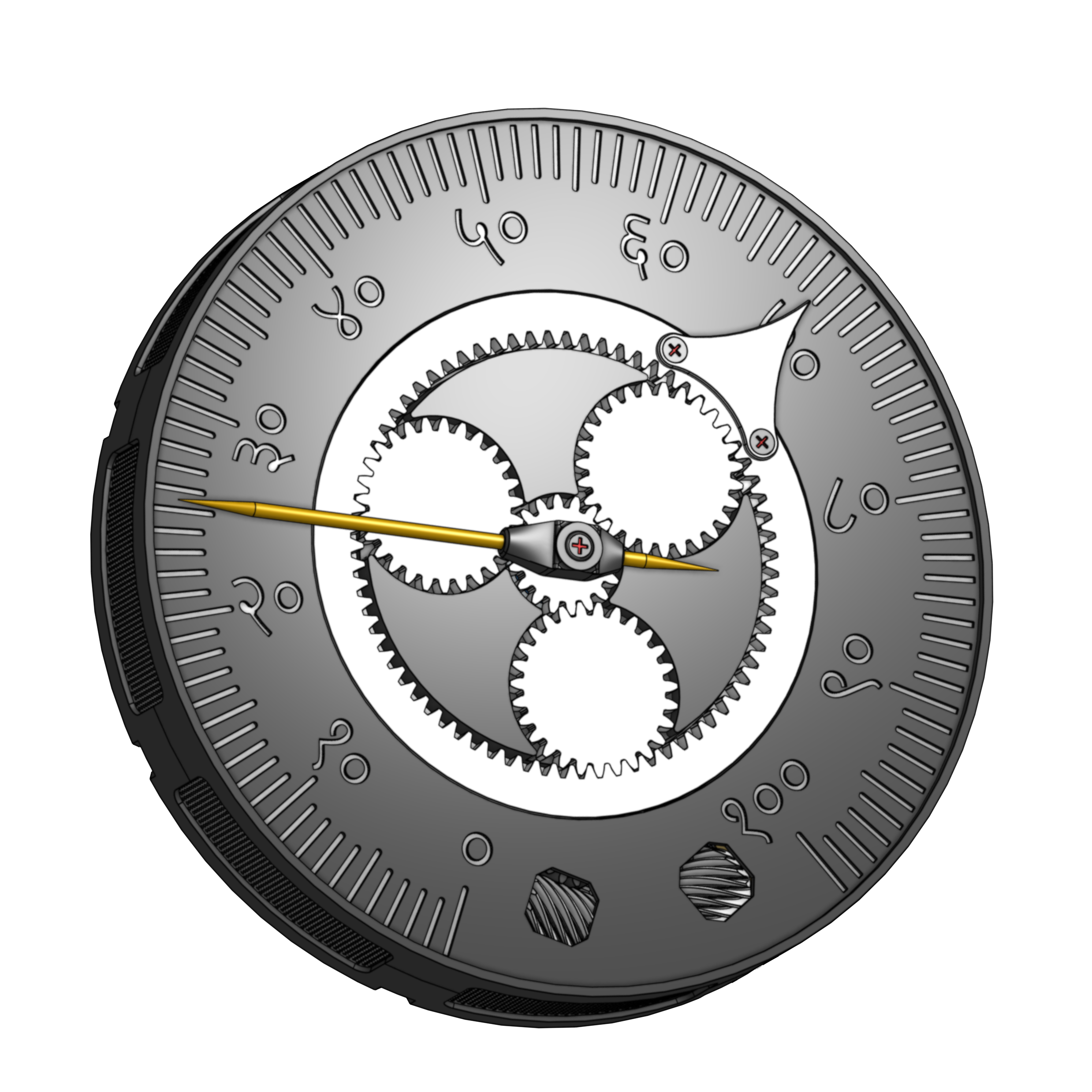
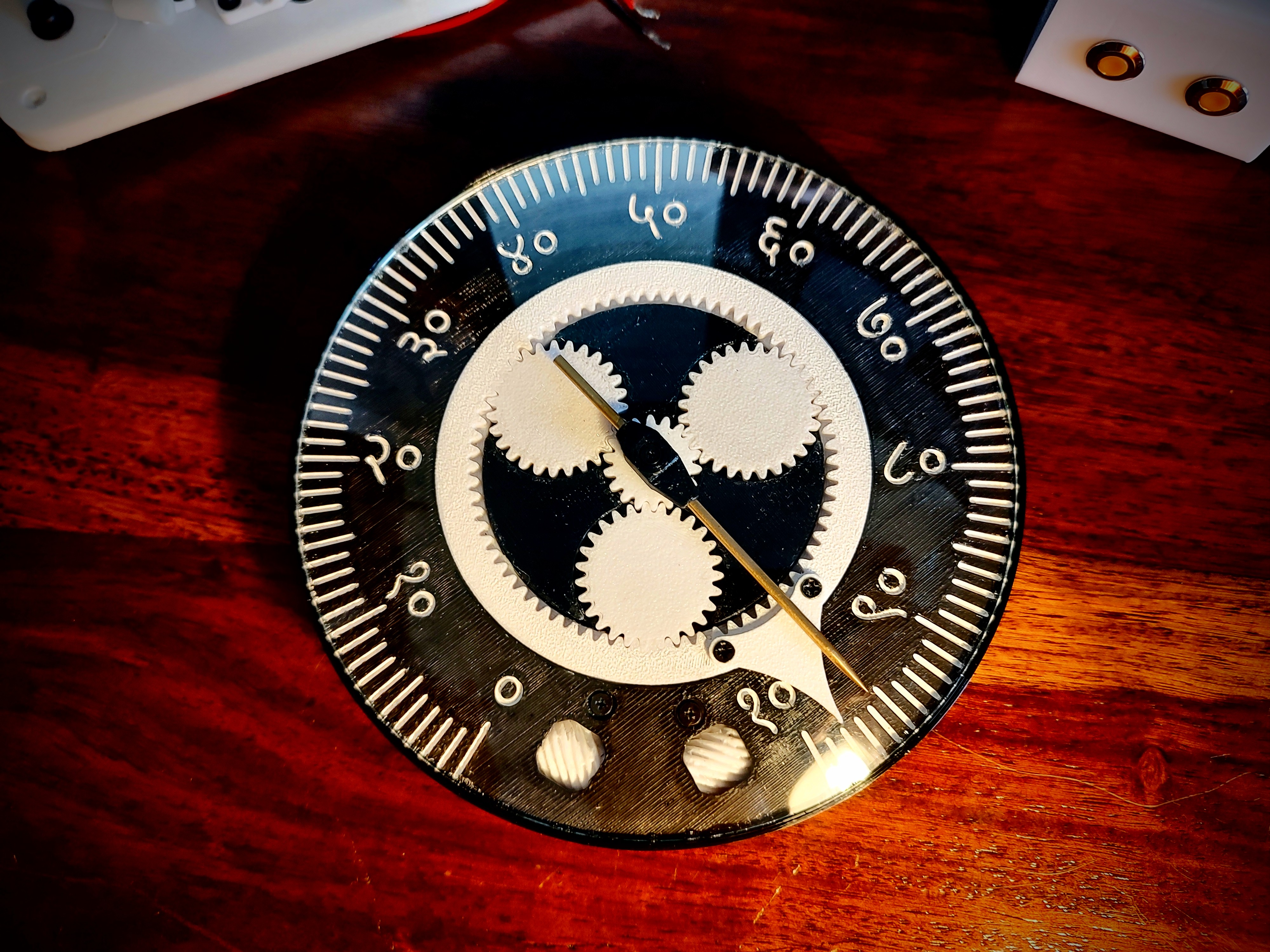
The Thermometer shows room temperature and dew point with two independent mechanical ticks, each driven by its own N20 motor and tracked by its own absolute encoder.
| Tick | Shows | Drive train |
|---|---|---|
| Tick 1 — brass rod | Room temperature | N20 → crossed helical gear → two 22T spur gears → tick |
| Tick 2 — planetary set | Dew point | N20 → crossed helical gear → helical ring gear → planetary set |
Both ticks are read 1 : 1 by AS5600 magnetic encoders on the main board, so the gauge always knows exactly where its needles are. Gear visibility and a symmetrical face were the top design priorities.
| Full Assembly | Both Ticks Engaged | Main Board |
|---|---|---|
 |  |  |
| Top Assembly | Bottom Assembly | Top Housing |
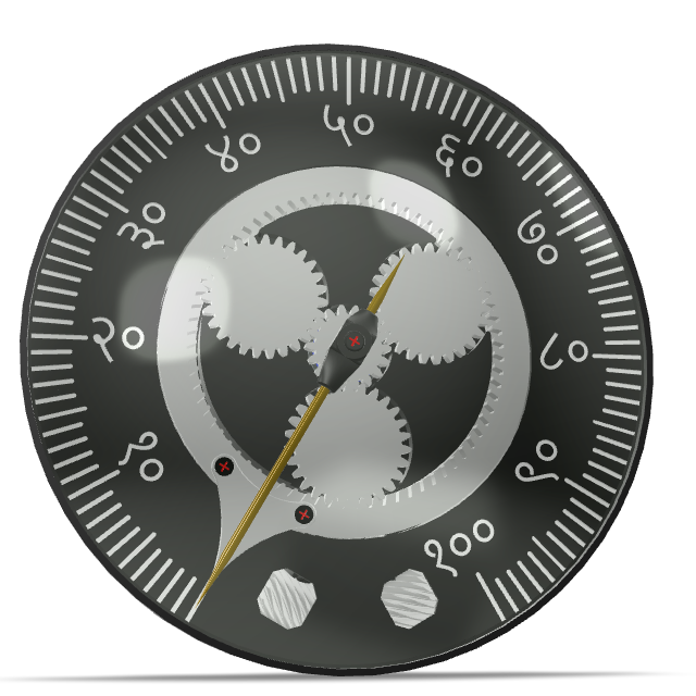 |  |  |
Want to spin these around? The blog post has interactive 3D viewers for every assembly.
For complete printing and assembly instructions, scroll all the way down to the 'Manufacturing' section on the official blog post: The Thermometer (AQI Board) Guide
[!TIP] Every part prints normally except the top housing, which has nuts embedded mid-print. The layer they sit on must be perfectly flat — use the Sharpie technique on the supports.
| Quantity | Item Description |
|---|---|
| 8x | M2 x 16 mm Hex Head Allen Type Screws |
| 8x | M2 Nut |
| 2x | N20 motor |
| 1x | Set of 3D printed parts (Found in the CAD/Printables folder) |
| 1x | Fully Assembled Circuit (Found in the Electronics folder) |
| 1x | 2mm Brass rod (Cut to size) |
| 6x | 15mm x 5mm N52 Neodymium magnets |
| 1x | 120mm x 120mm PC fan |
| 1x | 0.6mm PVC mesh (Cut to size) |
| 1x | 1 set of 5-pin pogo pin connector |
| 1x | SKF 688 Bearing |
| 2x | NMB MR74 Bearing |
| 2x | NMB MR63 Bearing |
| 1x | NMB MR126 Bearing |
| 4x | SKF 696 Bearing |
| Component | Role |
|---|---|
| Seeed Studio XIAO ESP32-C3 | Main controller |
| SHT40 | Temperature & humidity sensor (dew point is calculated from these) |
| AS5600 ×2 | Absolute magnetic encoders, one per tick |
| PCA9546A | 4-channel I²C multiplexer |
| DRV8833 | Dual H-bridge motor driver |
| DMP3007LK3 | P-MOSFET for reverse-polarity protection |
| USBLC6-2 | ESD protection |
Schematic PDF: Electronics/TheMainBoard_Schematic.pdf · KiCad project, custom symbol/footprint libraries, Gerbers and datasheets are all in Electronics/.
Built with PlatformIO on the Arduino framework for seeed_xiao_esp32c3.
cd Firmware/temperature_level_device
pio run -t upload
pio device monitor -b 115200| Command (over USART) | Response |
|---|---|
t | Reads the SHT40 and returns temperature and dew point as binary floats |
w | Moves the ticks to the latest temperature and dew point |
Between commands the gauge refreshes itself on its own, so it also works standalone.
Firmware/Testing Programs/ holds the bring-up sketches used along the way: motor silence tests (plain and PID), USART master communication, and a PCA9546A device scanner.
Thermometer/
├── CAD/
│   ├── Blender Projects/        # Source .blend files for every assembly
│   ├── GLB-GLTF FIles/          # Web-ready 3D models + model-viewer pages
│   ├── Printables/              # STL files to print
│   └── Step Files/              # STEP assemblies (with and without electronics)
├── Electronics/
│   ├── The Main Board/          # KiCad project + Gerber files
│   ├── Libraries/               # Custom KiCad symbols, footprints & 3D models
│   ├── Documentations/          # Component datasheets
│   └── TheMainBoard_Schematic.pdf
├── Firmware/
│   ├── temperature_level_device/     # Main firmware
│   ├── temperature_level_device_2/   # Alternate firmware revision
│   └── Testing Programs/             # Bring-up & test sketches
├── LICENSE.txt
└── README.md| Project | Description |
|---|---|
| Hygrometer | Analog humidity gauge with a globoid worm drive |
| Thermometer (you are here) | Temperature & dew point gauge with a planetary gear set |
| AQI Meter · VOC Meter | Coming soon |
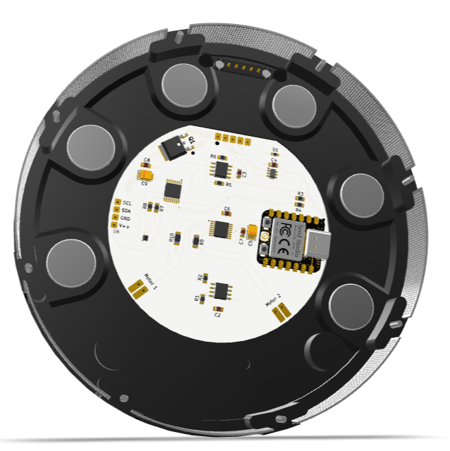
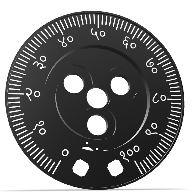
| Full Assembly | The Face |
|---|---|
 |  |
| The Mechanism | The Main PCB — Assembled | The Backside |
|---|---|---|
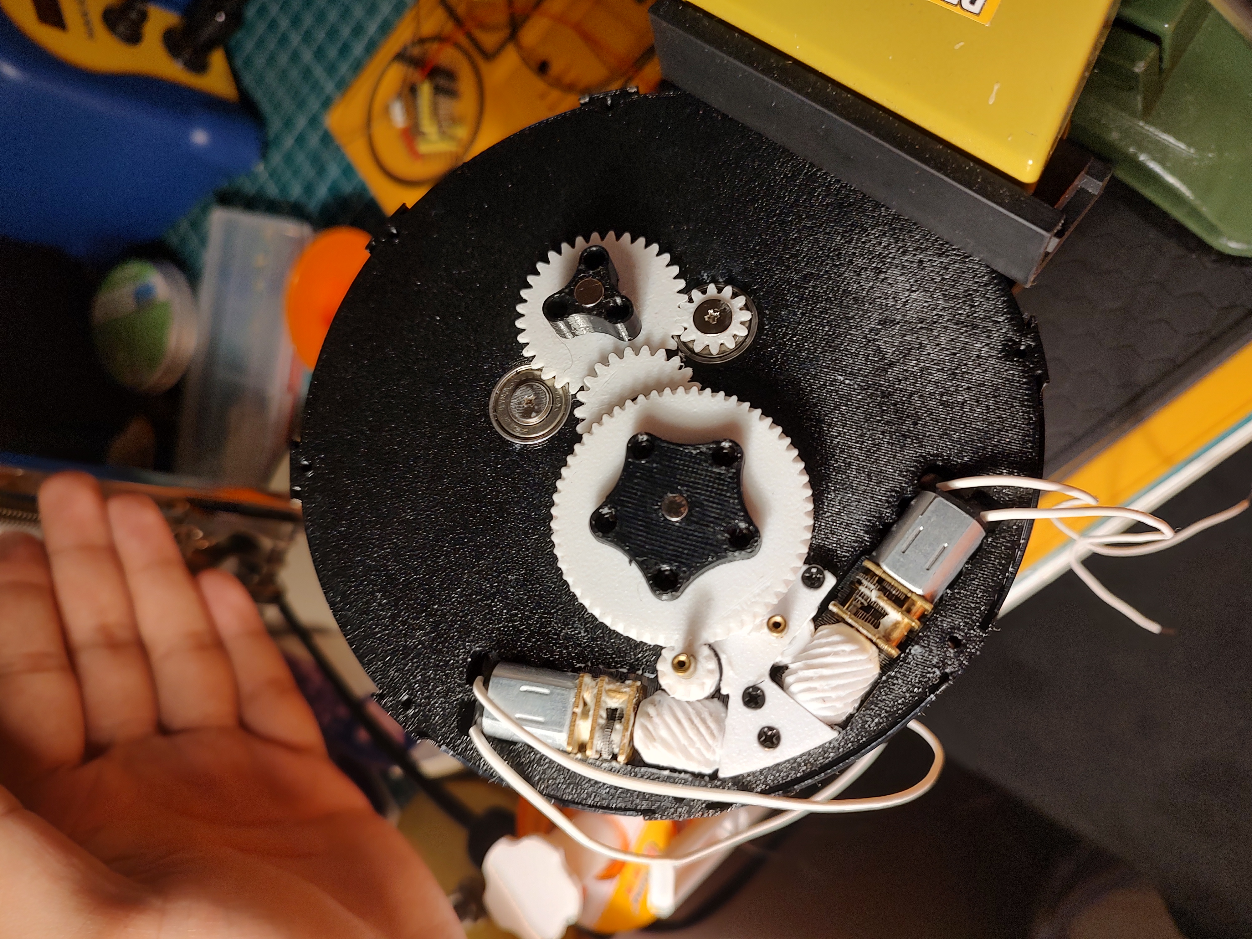 | 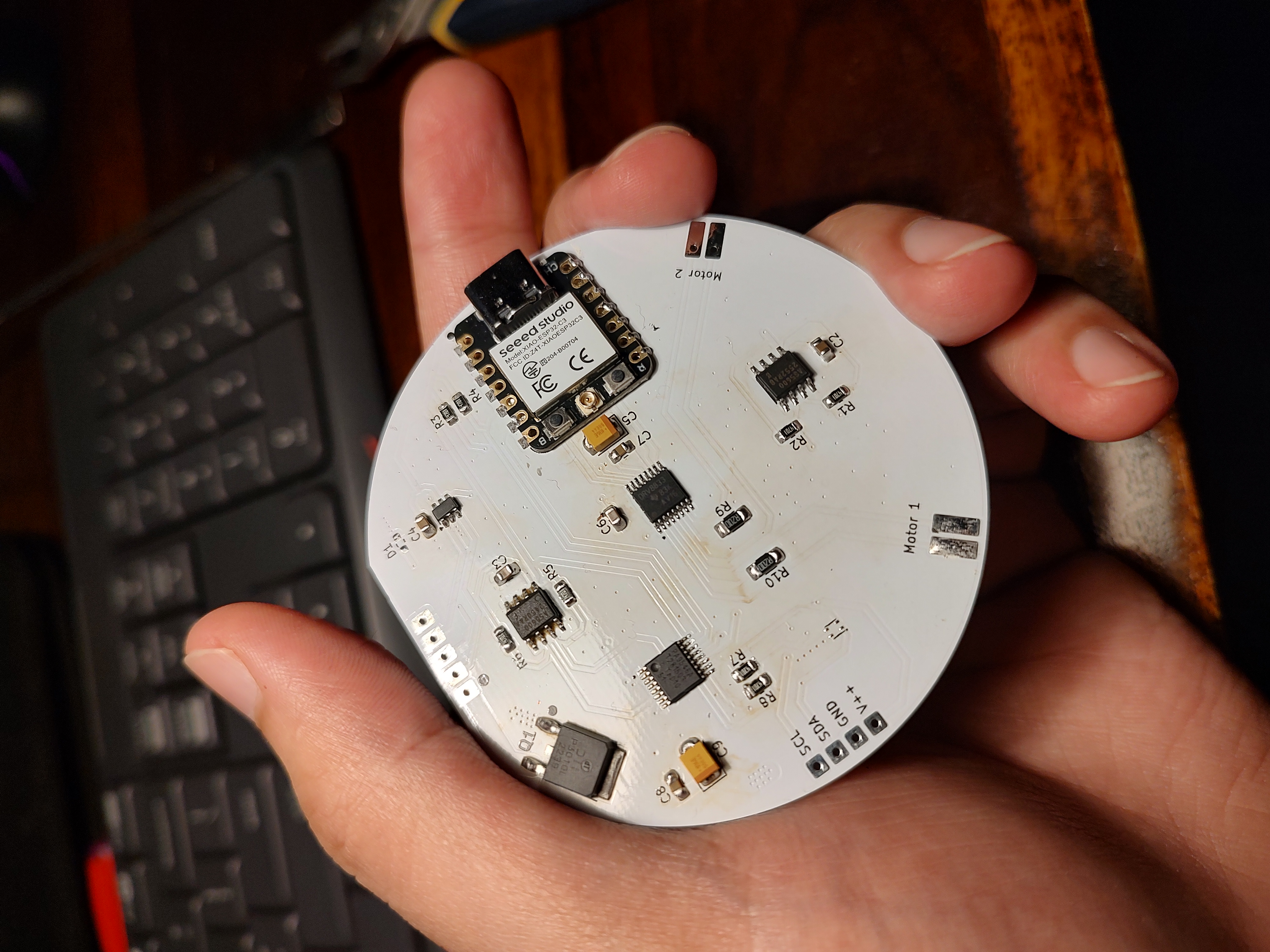 | 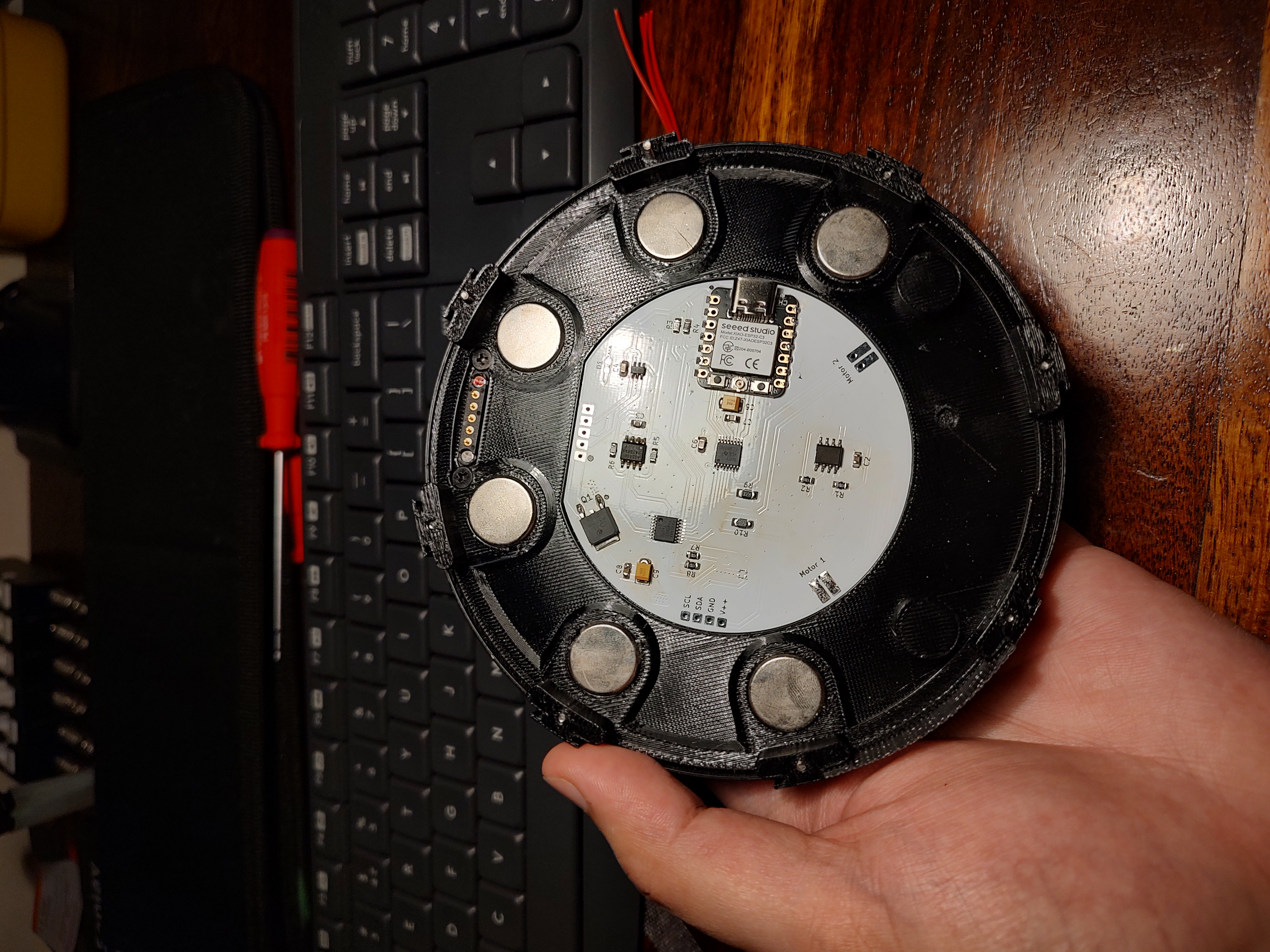 |
| The Internals | The Main PCB — Front & Back |
|---|---|
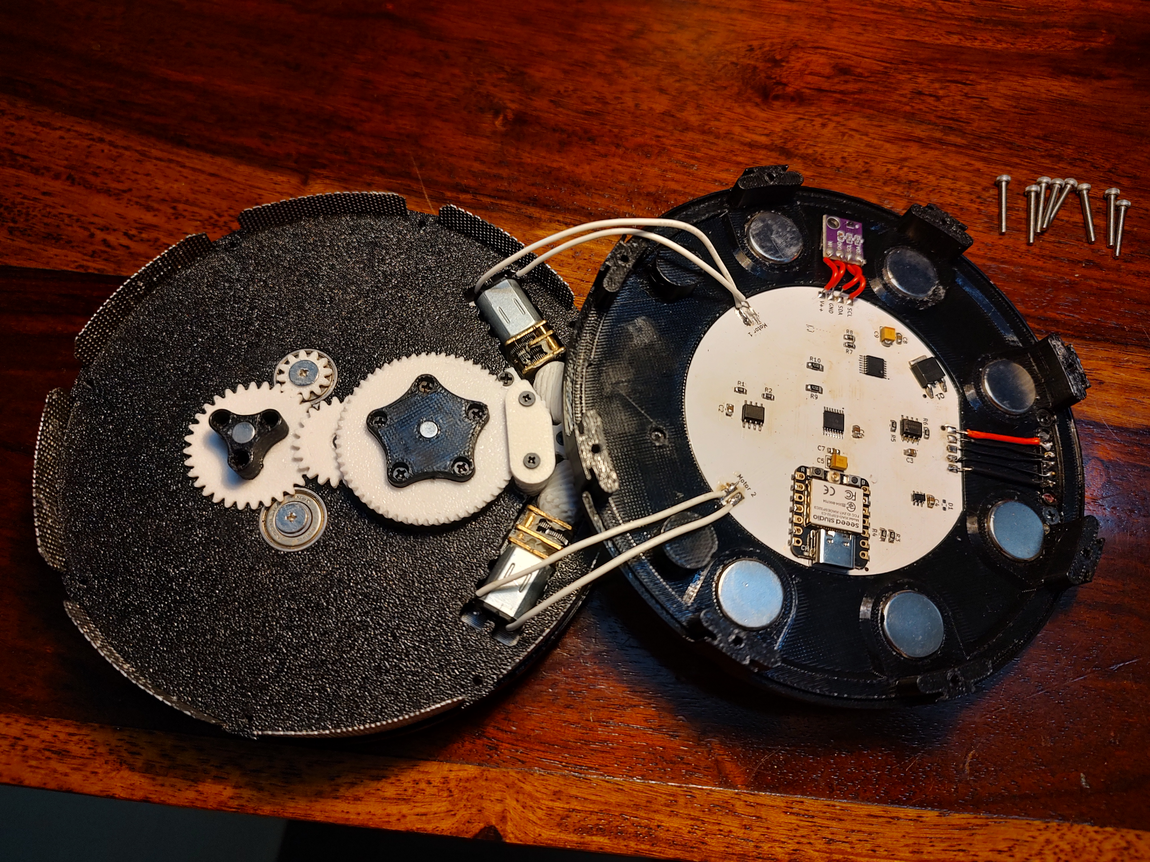 | 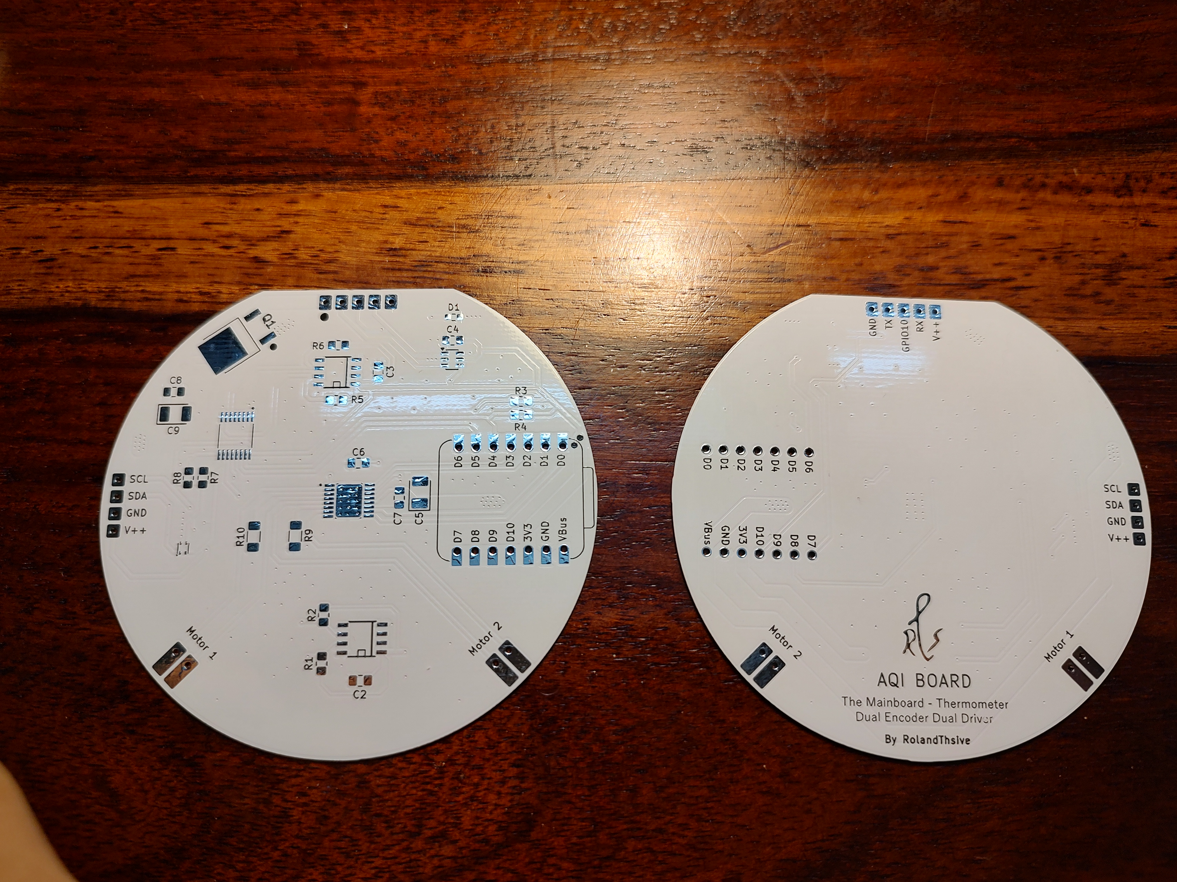 |
The Main Board Schematic
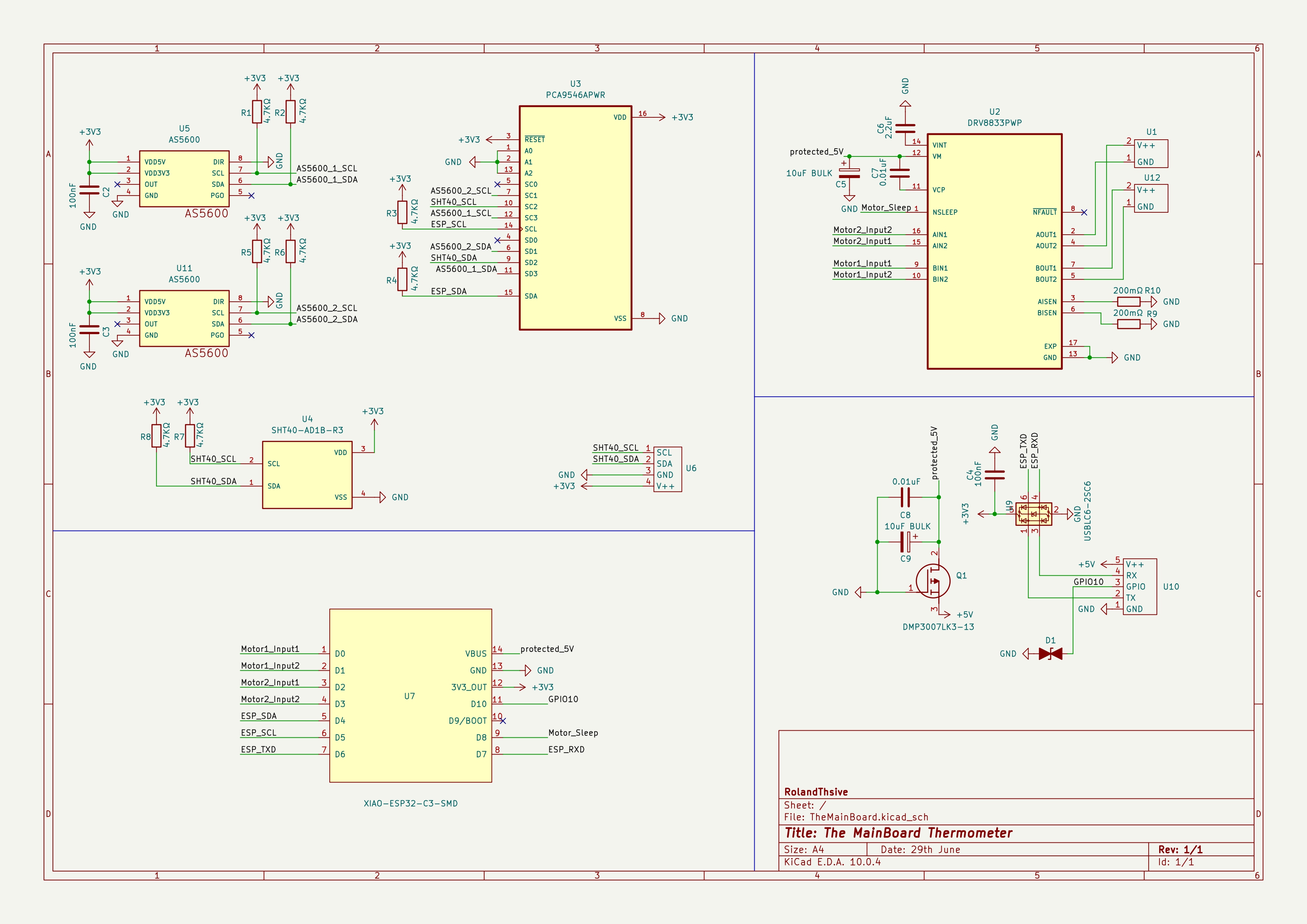
Click any picture to see it full size.

This work is licensed under a Creative Commons Attribution-NonCommercial-ShareAlike 4.0 International License.

Made with love by RolandThsive (@RolandThsive)
| Qty | Value | Footprint | References |
|---|---|---|---|
| 8 | 4.7KΩ | Resistor_SMD:R_0805_2012Metric_Pad1.20x1.40mm_HandSolder | R1, R2, R3, R4, R5, R6, R7, R8 |
| 3 | 100nF | Capacitor_SMD:C_0805_2012Metric_Pad1.18x1.45mm_HandSolder | C2, C3, C4 |
| 2 | 0.01uF | Capacitor_SMD:C_0805_2012Metric_Pad1.18x1.45mm_HandSolder | C7, C8 |
| 2 | 10uF BULK | Capacitor_Tantalum_SMD:CP_EIA-3528-21_Kemet-B_HandSolder | C5, C9 |
| 2 | 200mΩ | Resistor_SMD:R_1206_3216Metric_Pad1.30x1.75mm_HandSolder | R9, R10 |
| 2 | AS5600 | AS5600:SOIC8 | U5, U11 |
| 2 | ~ | WireToPCB_footprints:2PinsOut_foot | U1, U12 |
| 1 | 2.2uF | Capacitor_SMD:C_0805_2012Metric_Pad1.18x1.45mm_HandSolder | C6 |
| 1 | DMP3007LK3-13 | DMP3007LK3-13:DMP3007LK313 | Q1 |
| 1 | DRV8833PWP | DRV8833PWP:IC_DRV8833PWP | U2 |
| 1 | D_TVS_Filled | Resistor_SMD:R_0603_1608Metric_Pad0.98x0.95mm_HandSolder | D1 |
| 1 | PCA9546APWR | PCA9546APWR:SOP65P640X120-16N | U3 |
| 1 | SHT40-AD1B-R3 | SHT40-AD1B-R3:SHT4X | U4 |
| 1 | USBLC6-2SC6 | Package_TO_SOT_SMD:SOT-23-6 | U9 |
| 1 | XIAO-ESP32-C3-SMD | Seeed_Studio_XIAO_Series_footprints:XIAO-ESP32-C3-DIP | U7 |
| 1 | ~ | WireToPCB_footprints:5PinsOut_foot | U10 |
| 1 | ~ | WireToPCB_footprints:4WiresOut_foot | U6 |
It measures 29.3 × 68.9 mm and has 2 copper layers, 0.8 mm thick.
31 parts, built around the DRV8833PWP, PCA9546APWRE4, SHT40-AD1B-R3 and USBLC6-2SC6. The full list of its parts is on this page, with links to each part's symbol and footprint where PCBKit's library has them.
From the RolandThsive/Thermometer repository on GitHub, at the commit this page was made from: the board is Electronics/The Main Board/TheMainBoard/TheMainBoard.kicad_pcb and its schematic Electronics/The Main Board/TheMainBoard/TheMainBoard.kicad_sch. PCBKit opens the board in the browser, with nothing to install.
Its repository states no licence, so its author keeps all rights: ask RolandThsive before reusing the design.
codetiger/PowerTiger
Home power monitoring system - Monitoring energy consumption with better granularity

moclei/motion-play
Motion sensing project for fast moving objects moving through a plane. With directionality.

Norbixix/home-weather-station-esp32
ESP32-based low-power home weather station PCB project

arrow53/RoomTempHumidity
A local whole-house temperature and humidity monitor. USB-powered room sensors send measurements over Thread to a Raspberry Pi base unit, which stores history and presents a touchscreen dashboard without requiring a…

cegea/temperature_node_hw
PCB design for a temperature sensor based on SHT and ESP32

laemo10/SuperNicePCB
An integrated, multi-sensor UWB anchor PCB designed for real-time indoor object tracking (via Double-Sided Two-Way Ranging) and non-invasive human presence/occupancy monitoring.

xmyoot/esp32c6-ble-sensor-coin-cell
Ultra-compact 4-layer circular BLE sensor pod with ESP32-C6, CR2032 coin-cell power and environmental sensors

satomm1/Robot
This directory contains the electrical schematic for a breakout board for the Bosch BMI323 6-axis IMU. This IMU provides a 16 bit digital triaxial accelerometer, a 16 bit digital triaxial gyroscope, and a 16 bit digital…