4 layers50.8 × 22.9 mm
Bench stim wing
ThatguyCplus/throttleECU
STM32F411CE Throttle ECU — PID position control with AS5048A encoder, H-bridge motor, safety module
114 parts1

 robertxdx/ESP32S3PD15W
A 15 W USB-C powered ESP32-S3 LED-strip controller and development board.
ESP32 boardV1 is an open-source printed circuit board by robertxdx, from the robertxdx/ESP32S3PD15W repository on GitHub. It is a 4-layer board of 60 × 50 mm with 46 parts on 57 nets, routed with 346 tracks and 123 vias.
It is built around the SN74HC125PWR-TP, ESP32-S3-WROOM-1-N4 and AP63203WU, with the USBLC6-2P6, 0402F104M500NT and PTS636SK25SMTRLFS among its other parts. Its parts include 14 capacitors, 8 resistors, 5 diodes, 5 connectors and 5 switches. It belongs with the microcontroller boards boards and the ESP32 boards of this library.


A 15 W USB-C powered ESP32-S3 LED-strip controller and development board.
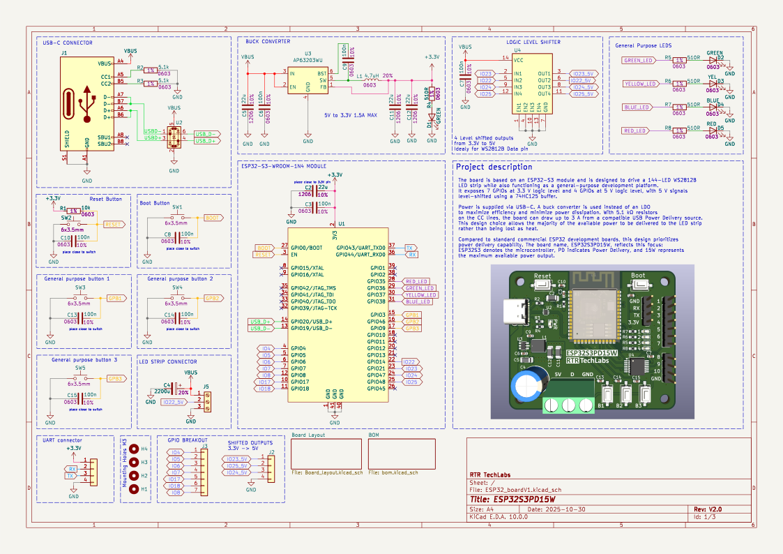
ESP32S3PD15W is a compact ESP32-S3-WROOM-1 board built to drive a 144-LED WS2812B strip while still behaving like a practical development platform. It prioritizes power delivery over the usual low-current dev-board formula: USB-C input, an efficient buck converter, level-shifted 5 V data outputs, and accessible GPIO for experiments.
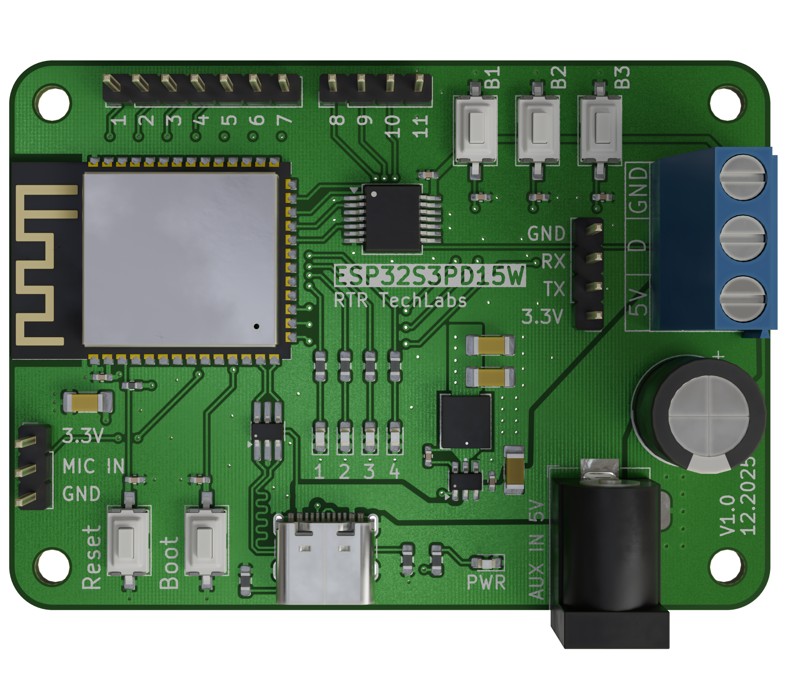
Most ESP32 development boards are convenient for firmware work but awkward when the project needs real 5 V power for addressable LEDs. This board is designed around that use case:
| Area | Details |
|---|---|
| MCU | ESP32-S3-WROOM-1 module |
| Power input | USB-C, designed for up to 5 V / 3 A sources |
| Power output focus | Up to 15 W available for LED-strip use |
| 3.3 V rail | AP63203 buck converter |
| LED/data outputs | 4x 5 V level-shifted GPIO via 74AHCT125 |
| Native GPIO | 7x exposed 3.3 V GPIO |
| USB protection | USBLC6-2P6 ESD protection |
| User controls | Boot, reset, and general-purpose buttons |
| Status indicators | Multiple onboard LEDs |

| Path | Purpose |
|---|---|
ESP32_boardV1/ESP32_boardV1.kicad_pro | KiCad project |
ESP32_boardV1/ESP32_boardV1.kicad_sch | Main schematic |
ESP32_boardV1/ESP32_boardV1.kicad_pcb | PCB layout |
ESP32_boardV1/production/ | BOM, position files, IPC netlist, and fabrication package |
Design documentation/ | Design notes and diagrams |
docs/images/ | README-ready board and schematic imagery |
The production folder contains generated assembly and fabrication collateral, including:
Review the KiCad files and production outputs before ordering boards, especially if component footprints or USB-C power assumptions change.
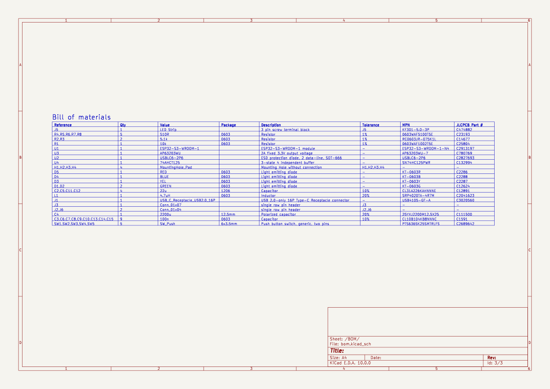
| Qty | Value | Footprint | References |
|---|---|---|---|
| 9 | 100n | Capacitor_SMD:C_0603_1608Metric | C3, C6, C7, C8, C9, C10, C13, C14, C15 |
| 5 | 510R | Resistor_SMD:R_0603_1608Metric_Pad0.98x0.95mm_HandSolder | R4, R5, R6, R7, R8 |
| 5 | SW_Push | Button_Switch_SMD:SW_Tactile_SPST_NO_Straight_CK_PTS636Sx25SMTRLFS | SW1, SW2, SW3, SW4, SW5 |
| 4 | 22u | Inductor_SMD:L_1206_3216Metric_Pad1.22x1.90mm_HandSolder | C2, C5, C11, C12 |
| 4 | MountingHole_Pad | MountingHole:MountingHole_3.2mm_M3 | H1, H2, H3, H4 |
| 2 | 5.1k | Resistor_SMD:R_0603_1608Metric_Pad0.98x0.95mm_HandSolder | R2, R3 |
| 2 | Conn_01x04 | Connector_PinHeader_2.54mm:PinHeader_1x04_P2.54mm_Vertical | J2, J6 |
| 2 | GREEN | LED_SMD:LED_0603_1608Metric_Pad1.05x0.95mm_HandSolder | D1, D2 |
| 1 | 10k | Resistor_SMD:R_0603_1608Metric | R1 |
| 1 | 2200u | Capacitor_THT:CP_Radial_D10.0mm_P5.00mm | C4 |
| 1 | 4.7uH | Inductor_SMD:IND_SRP4020TA-1R0M_BRN | L1 |
| 1 | 74AHCT125 | Package_SO:SSOP-14_5.3x6.2mm_P0.65mm | U4 |
| 1 | AP63203WU | Package_TO_SOT_SMD:TSOT-23-6 | U3 |
| 1 | BLUE | LED_SMD:LED_0603_1608Metric_Pad1.05x0.95mm_HandSolder | D4 |
| 1 | Conn_01x07 | Connector_PinHeader_2.54mm:PinHeader_1x07_P2.54mm_Vertical | J3 |
| 1 | ESP32-S3-WROOM-1 | PCM_Espressif:ESP32-S3-WROOM-1 | U1 |
| 1 | LED Strip | TerminalBlock_Phoenix:TerminalBlock_Phoenix_MKDS-1,5-3-5.08_1x03_P5.08mm_Horizontal | J5 |
| 1 | RED | LED_SMD:LED_0603_1608Metric_Pad1.05x0.95mm_HandSolder | D5 |
| 1 | USBLC6-2P6 | Package_TO_SOT_SMD:SOT-666 | U2 |
| 1 | USB_C_Receptacle_USB2.0_16P | Connector_USB:USB_C_Receptacle_GCT_USB4105-xx-A_16P_TopMnt_Horizontal | J1 |
| 1 | YEL | LED_SMD:LED_0603_1608Metric_Pad1.05x0.95mm_HandSolder | D3 |
ThatguyCplus/throttleECU
STM32F411CE Throttle ECU — PID position control with AS5048A encoder, H-bridge motor, safety module


Mowibox/chromapi_motherboard
Raspberry Pi control HAT dedicated to the quadruped robot Chromapi.

ratmuds/spark
The PCB files for this project. The gerber and other PCBA files are in the production folder.

AresEnsea/2526_Projet2A_AresCFR
Ce repository GitHub regroupe l'ensemble des projets et documents réalisés par l'équipe Ares pour la Coupe de France de Robotique 2026.

sedlak477/owl-hardware
Hardware design files and build instructions for the OWL platform

MukeshSethy/micromouse-runner
This is my repo for the first version of full size micromouse development.

HeyPCB/badge-blob
Blob, the social battery badge: The name badge that tells people whether to come say hi. KiCad 10, heypcb.ai merch.
It measures 60 × 50 mm and has 4 copper layers, 1.6 mm thick.
46 parts, built around the SN74HC125PWR-TP, ESP32-S3-WROOM-1-N4, AP63203WU and USBLC6-2P6. The full list of its parts is on this page, with links to each part's symbol and footprint where PCBKit's library has them.
From the robertxdx/ESP32S3PD15W repository on GitHub, at the commit this page was made from: the board is ESP32_boardV1/ESP32_boardV1.kicad_pcb and its schematic ESP32_boardV1/Board_layout.kicad_sch. PCBKit opens the board in the browser, with nothing to install.
Its repository states no licence, so its author keeps all rights: ask robertxdx before reusing the design.