
2 layers100 × 100 mm
CPU 6809 board
roberto314/Unicomp2
A modular 8-bit Computer able to recreate (nearly) every Retro computer of the late 70s to mid 80s.
78 parts1

 roberto314/Unicomp21
A modular 8-bit Computer able to recreate (nearly) every Retro computer of the late 70s to mid 80s.
SplitterBoard is an open-source printed circuit board by roberto314, from the roberto314/Unicomp2 repository on GitHub. It is a 2-layer board of 100 × 100 mm with 23 parts on 102 nets, routed with 1,490 tracks and 74 vias.
It is built around the SN74LVC245ANSR. Its parts include 12 connectors, 3 ICs and 2 capacitors. It belongs with the retro computing and games boards of this library.
A modular 8-bit Computer able to recreate (nearly) every microcomputer of the mid 70s to early 80s in Hardware without FPGAs (although an FPGA can be added). Can also be used as a teaching tool for:
It is different from other designs because of these points:
Version 2.00
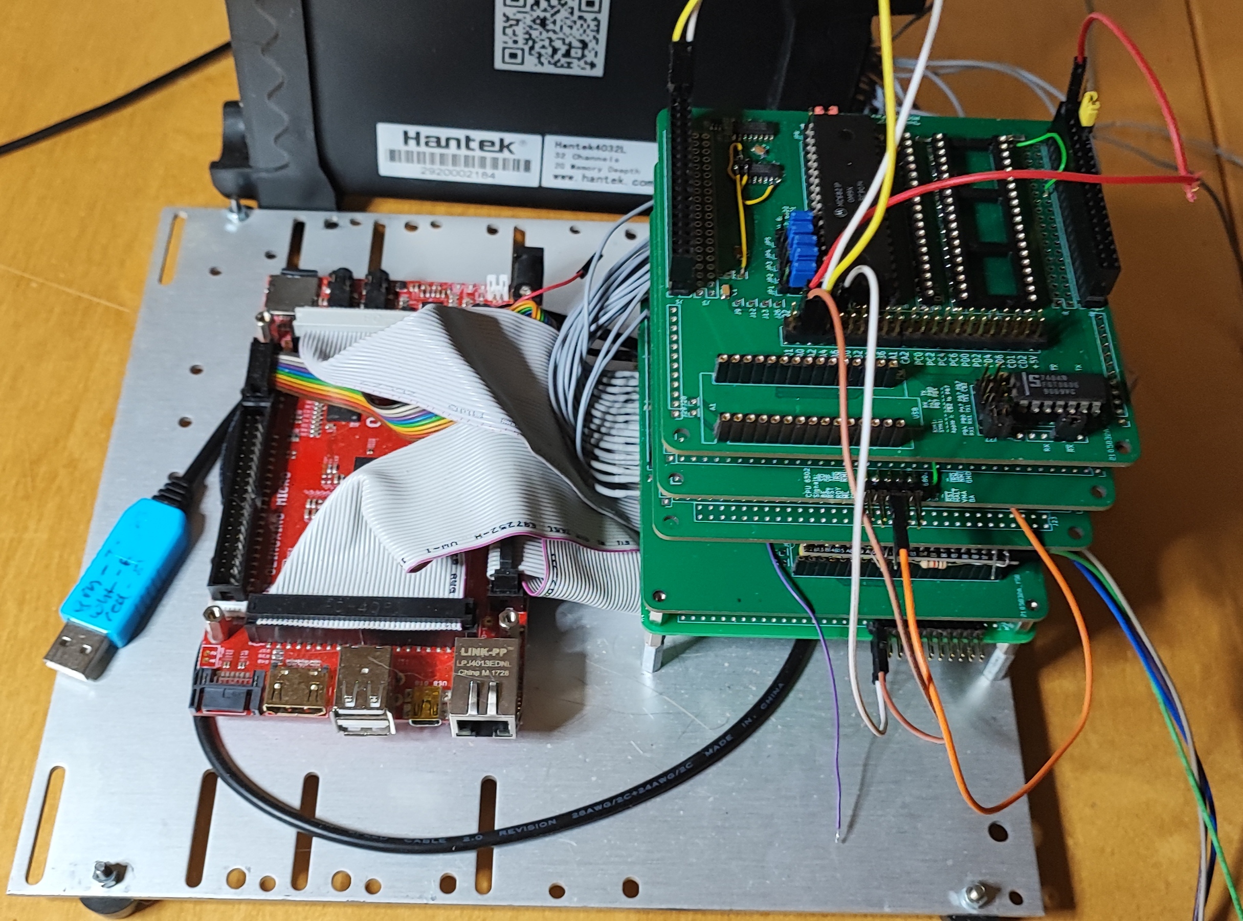
Unicomp plus Logic Analyzer:
Input board:
CPU board:
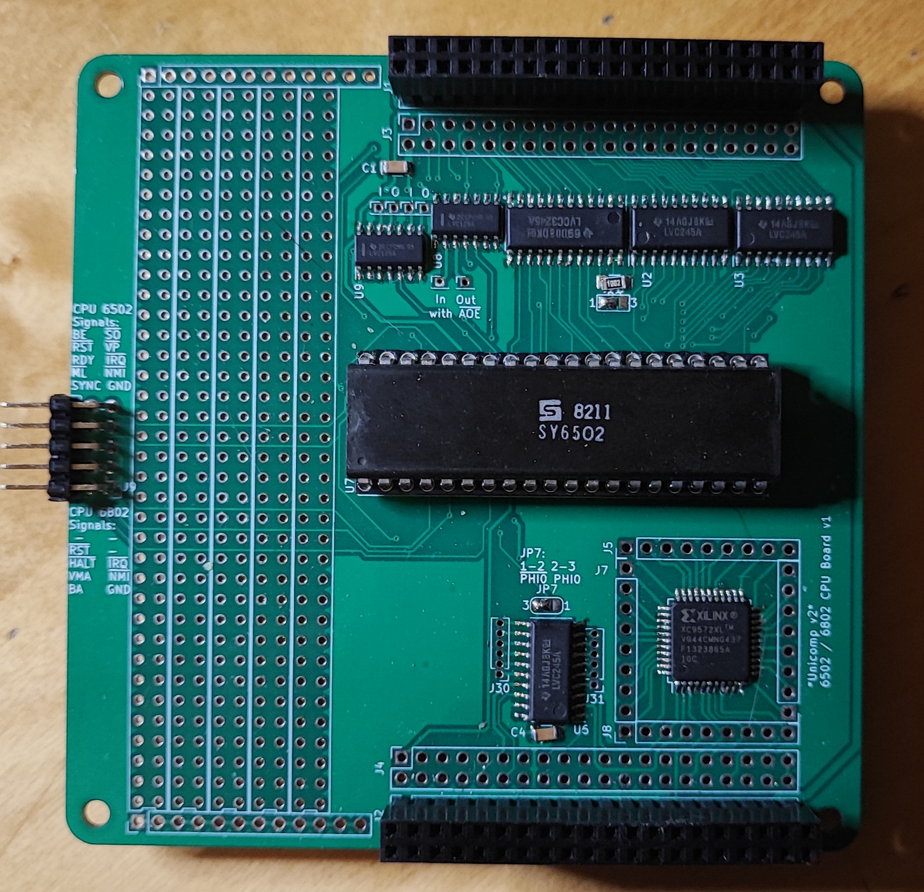
6502 Board:
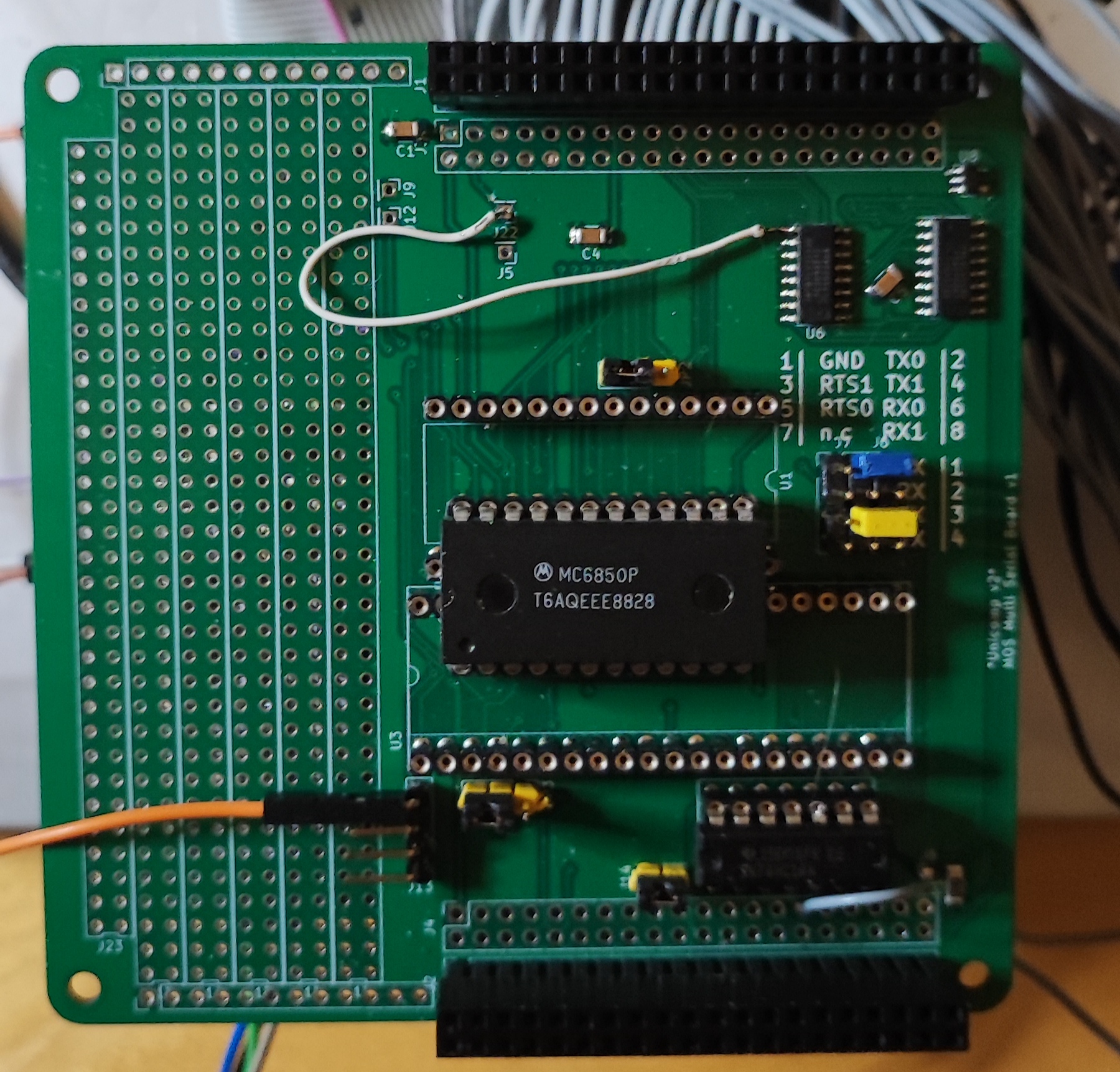
Multi Serial Board:
Multi Parallel boaŕd:
RAMROM board:
Prototype board:
MAX-II (EPM240) board:
self made module:
The configuration is done with 128kx8 fast ram on the peripheral boards. These will be configured from the STM32F401. One bit is for one Output (of which there are two) and for two addresses (resolution for chipselect is 2 bytes). The cs = 15 is for writing the main RAM, cs = 14 is the chip select for the RAMROM board. The rest is free. With two chip select lines per board these are 28 lines. One byte in the mapping ram has the following format:
| 7 | 6 | 5 | 4 | 3 | 2 | 1 | 0 | Bits |
|---|---|---|---|---|---|---|---|---|
| 7,6 | 5,4 | 3,2 | 1,0 | 7,6 | 5,4 | 3,2 | 1,0 | Address |
| /CS0 | /CS0 | /CS0 | /CS0 | /CS1 | /CS1 | /CS1 | /CS1 | Peripheral |
| /CS | /CS | /CS | /CS | WP | WP | WP | WP | RAMROM |
So 128k are good for 128kx8 Bytes of Addressspace (=1MByte) The data gets transferred to the STM32 in compact form. Only the Start address, the chipselect and the bitmask (which is Low-active) for every addresses where someting changes are transferred. A 0xFE for a bitmask means Peripheral chipselect /CS1 is active for two addresses. If the board is the RAMROM board the low nibble is Writeprotect (Hi-active).
A simple configuration block looks líke this:
(RAM: 0-9FFF, ACIA0: A000-A001, ACIA1: A010-A011, ROM: C000-FFFF)

00 00 00 0E 00  :  RAM
00 A0 00 00 EF  :  ACIA0
00 A0 02 FF FF  :  HOLE
00 A0 10 00 FE  :  ACIA1
00 A0 12 FF FF  :  HOLE
00 C0 00 0E 0F  :  ROM
01 00 00 FF FF  :  END
00 00 00 : noting further| Name | prim. IO | chips used | os | weblink |
|---|---|---|---|---|
| Grant Searle 6502 board | serial | MOS6502, MC6850 | OSI Basic | Link: http://searle.x10host.com/6502/Simple6502.html |
| Daryl Rictor 6502 board | serial | MOS6502, R6551 | SBC-2 (monitor only) | Link: https://sbc.rictor.org/info2.html |
| Daryl Rictor 6502 board | serial | MOS6502, MC6850 | SBC-2 (monitor only) | Link: https://sbc.rictor.org/info2.html |
| SYM1 | serial | MOS6502, UM6532 | SYM1 ( +BASIC +RAE) | Link: http://retro.hansotten.nl/6502-sbc/synertek-sym-ktm/sym-1/ |
| KIM1 | serial | MOS6502, UM6532 | KIM1 | Link: http://retro.hansotten.nl/6502-sbc/kim-1-manuals-and-software/ |
| Apple I | serial | MOS6502, MĆ6821 (plus Arduino) | Wozmon + BASIC | Link: http://retro.hansotten.nl/6502-sbc/apple-1/ |
| Motorola MEK D2 | serial | MC6802, MĆ6850 | newbug, xswtbug, mondeb | Link: https://www.retrotechnology.com/restore/smithbug.html |
| Motorola MEK D1 | serial | MC6802, MĆ6821 (plus Arduino) | Mikbug | Link: https://www.retrotechnology.com/restore/smithbug.html |
| Heathkit ET3400 | serial | MC6802, MĆ6850 | MITS BASIC, TSC MicroBASIC,... | Link: https://github.com/jefftranter |
| SWTPC 6800 | serial | MC6802, MĆ6821 (plus Arduino) | Mikbug | Link: https://deramp.com/swtpc.com/ |
| SWTPC 6800 | serial | MC6802, MĆ6850 | SWTBUG, SWTBUGA, Mondeb, xSWTBUG | Link: https://deramp.com/swtpc.com/ |
| DREAM 6800 | BAS (Video) | MC6802, MAX-II | DREAM operating System (Chip8) | Link: http://www.mjbauer.biz/DREAM6800.htm |
| HD6303 Board (Eric Klaus) | serial | HD6303 | Monitor +BASIC | Link: https://sites.google.com/site/ericmklaus/projects-1/hd6303cpuboard |
| MC3 Computer | serial | HD6303 | Monitor | Link: https://www.waveguide.se/?article=mc3-a-diy-8-bit-computer |
| Psion Organizer I | LCD | HD6303 | Psion OS | Link: https://www.jaapsch.net/psion/index.htm |
I uses an olimex A20 SBC (olinuxino A20) which has a lot of peripherals (4x UART, 2x SPI, 2x I2C, a lot of GPIOs, SATA, 2x SDCARD, VGA, HDMI, LAN,...) and it is open hardware. The board is connected with three 40 pin cables (like old IDE cables) plus two 10 pin cables to the input board.
To access all the peripherals i use python with the pyA20 library here: https://pypi.org/project/pyA20/
The debian image (bullseye minimal) can be found at: http://images.olimex.com/release/a20/
To configure the image after downloading there are helper scripts in the unicomp folder under: olimex Board/config
I use fbterm and tmux for a nice terminal output. Here are some pictures:
tmux main window:
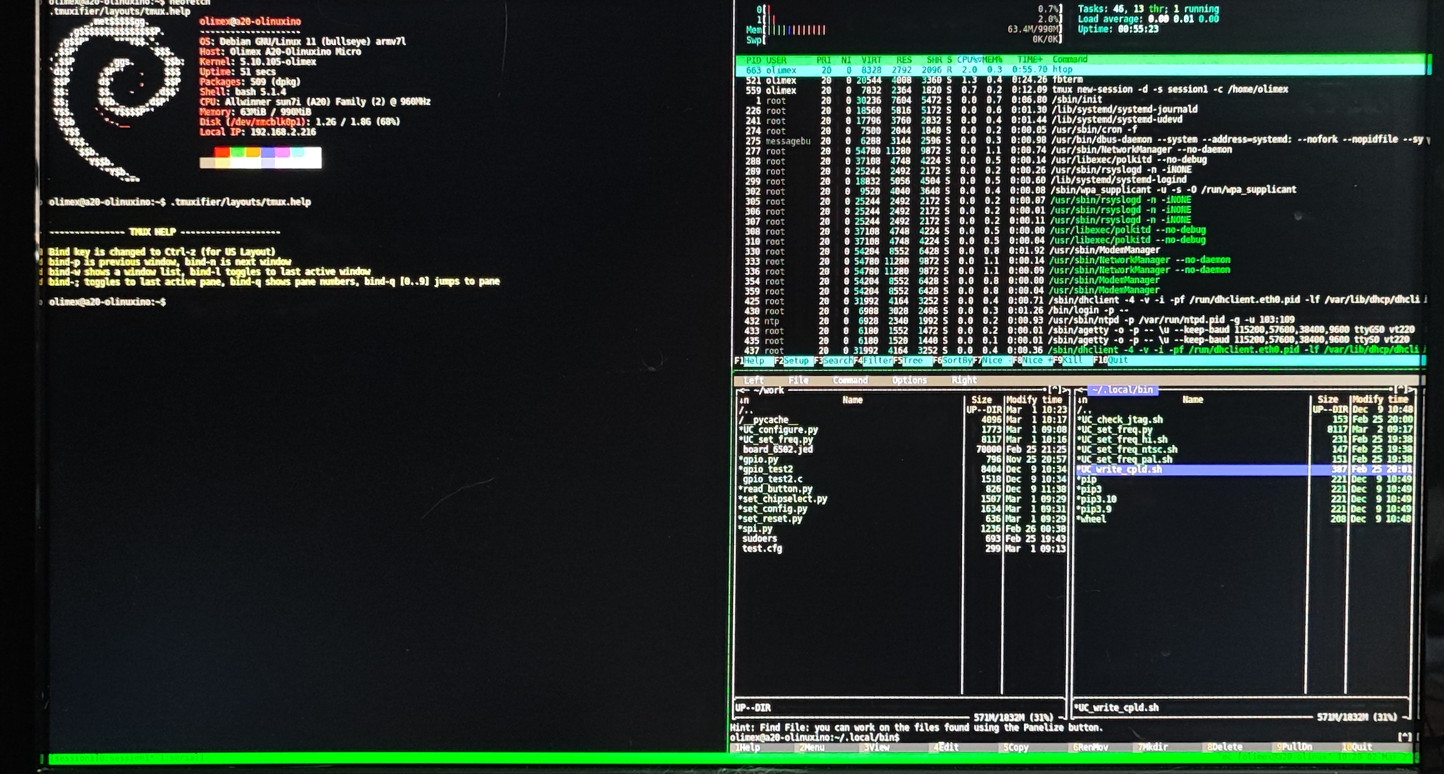
tmux serial window:
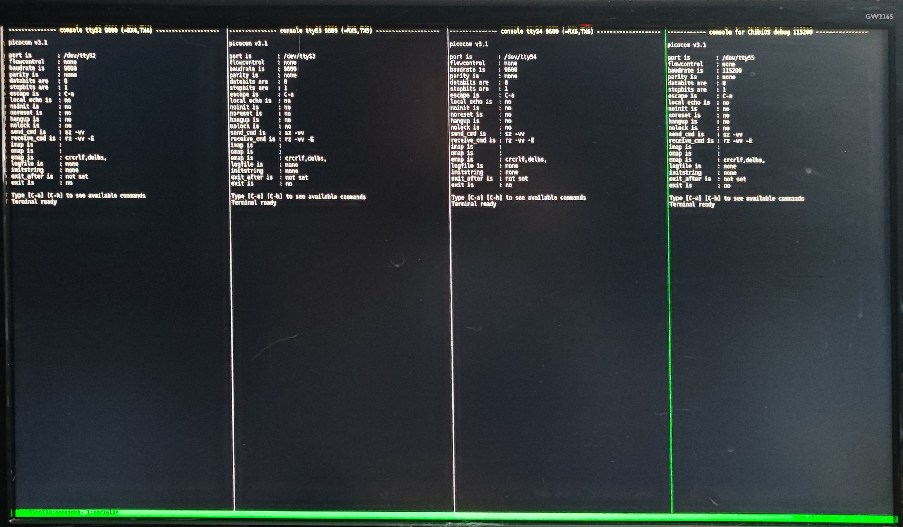
-- all scripts have to be executed with sudo bacause of direct hardware access!
set_reset.py [0,1,xx]
UC_check_jtag.sh
UC_write_cpld.sh [0..?] [.jed file]
Prepare new SD-Card:
compiling the vhdl (or verilog) code must be done on a computer with the Xilinx ISE 14.7 toolchain installed. Link: https://www.xilinx.com/support/download/index.html/content/xilinx/en/downloadNav/vivado-design-tools/archive-ise.html
compiling itself can be done inside ISE or with the supplied makefile (look inside the bord directory in cpld firmware)
a simple make will compile the firmware and a make transfer will transfer the file to the sbc (if you changed the ip address to your address inside the makefile and the path inside project.cfg)
on the sbc in the work folder one can find the .jed file. For programming type: UC_write_cpld [JTAG-position] [filename.jed]
| Qty | Value | Footprint | References |
|---|---|---|---|
| 4 | MountingHole | MountingHole:MountingHole_3.2mm_M3 | H1, H2, H3, H4 |
| 3 | SN74LVC245ANSR | Package_SO:SO-20_5.3x12.6mm_P1.27mm | U1, U2, U4 |
| 2 | 100n | Capacitor_SMD:C_1206_3216Metric | C4, C5 |
| 2 | BUS-Angled | Connector_PinHeader_2.54mm:PinHeader_2x20_P2.54mm_Horizontal | J5, J6 |
| 2 | BUS-Master | Connector_PinSocket_2.54mm:PinSocket_2x20_P2.54mm_Vertical | J1, J2 |
| 2 | BUS-Master-BO | Connector_PinSocket_2.54mm:PinSocket_2x20_P2.54mm_Vertical | J3, J4 |
| 2 | Conn_01x03 | Connector_PinHeader_2.54mm:PinHeader_1x03_P2.54mm_Vertical | J11, J12 |
| 2 | Conn_01x21 | Connector_PinHeader_2.54mm:PinHeader_1x21_P2.54mm_Vertical | J7, J8 |
| 1 | . | Jumper:SolderJumper-3_P1.3mm_Open_Pad1.0x1.5mm_NumberLabels | JP1 |
| 1 | GND | Connector_PinHeader_2.54mm:PinHeader_2x03_P2.54mm_Vertical | J10 |
| 1 | VCC | Connector_PinHeader_2.54mm:PinHeader_2x03_P2.54mm_Vertical | J9 |
| 1 | Vcc | Jumper:SolderJumper-3_P1.3mm_Open_RoundedPad1.0x1.5mm_NumberLabels | JP2 |
It measures 100 × 100 mm and has 2 copper layers, 1.6 mm thick.
23 parts, built around the SN74LVC245ANSR. The full list of its parts is on this page, with links to each part's symbol and footprint where PCBKit's library has them.
From the roberto314/Unicomp2 repository on GitHub, at the commit this page was made from: the board is Splitter Board/schematic/SplitterBoard/SplitterBoard-backups/SplitterBoard-2023-07-18_191943_v1.0/SplitterBoard.kicad_pcb. PCBKit opens the board in the browser, with nothing to install.
Its repository states no licence, so its author keeps all rights: ask roberto314 before reusing the design.
roberto314/Unicomp2
A modular 8-bit Computer able to recreate (nearly) every Retro computer of the late 70s to mid 80s.

roberto314/Unicomp2
A modular 8-bit Computer able to recreate (nearly) every Retro computer of the late 70s to mid 80s.

roberto314/Unicomp2
A modular 8-bit Computer able to recreate (nearly) every Retro computer of the late 70s to mid 80s.

roberto314/Unicomp2
A modular 8-bit Computer able to recreate (nearly) every Retro computer of the late 70s to mid 80s.

roberto314/Unicomp2
A modular 8-bit Computer able to recreate (nearly) every Retro computer of the late 70s to mid 80s.

roberto314/Unicomp2
A modular 8-bit Computer able to recreate (nearly) every Retro computer of the late 70s to mid 80s.

roberto314/Unicomp2
A modular 8-bit Computer able to recreate (nearly) every Retro computer of the late 70s to mid 80s.

roberto314/Unicomp2
A modular 8-bit Computer able to recreate (nearly) every Retro computer of the late 70s to mid 80s.

roberto314/Unicomp2
A modular 8-bit Computer able to recreate (nearly) every Retro computer of the late 70s to mid 80s.

roberto314/Unicomp2
A modular 8-bit Computer able to recreate (nearly) every Retro computer of the late 70s to mid 80s.

roberto314/Unicomp2
A modular 8-bit Computer able to recreate (nearly) every Retro computer of the late 70s to mid 80s.

roberto314/Unicomp2
A modular 8-bit Computer able to recreate (nearly) every Retro computer of the late 70s to mid 80s.

roberto314/Unicomp3
A modular 8-bit Computer able to recreate (nearly) every Retro computer of the late 70s to mid 80s.


google/mozc-devices
Circuit diagrams and firmware source code for Gboard DIY keyboards


