Skip to the content
PCBKitNew board
6 layers16.5 × 21.6 mmClock Addon, the printed circuit board in 3D

A reverse Polish notation calculator with added features such as comparisons, branching, and custom recursive operators taken from the Clac project from the 15-122 course at Carnegie Mellon University. The project is built around a 6502 microprocessor with a custom architecture to reduce CPU load by making peripherals operate asyncronously.

Size
16.5 × 21.6 mm
Copper layers
6
Thickness
1.6 mm
Parts
7
Nets
9
Pads
24
Tracks, vias
31, 0
Pours
4
Routed
Yes
KiCad
KiCad 8.0 (file 20240108)
Created
10 Sep 2024
Updated
17 Jul 2026

Overview

Clock Addon is an open-source printed circuit board by Robert-Mones, from the Robert-Mones/Claculator repository on GitHub. It is a 6-layer board of 16.5 × 21.6 mm with 7 parts on 9 nets, routed with 31 tracks and 0 vias.

It is built around the NE555P. Its parts include 2 capacitors, 2 resistors, 1 IC, 1 diode and 1 connector. It belongs with the lEDs and displays boards of this library.

Main components

1

README

README.md

Claculator

A reverse Polish notation calculator with added features such as comparisons, branching, and custom recursive operators taken from the Clac project from the 15-122 course at Carnegie Mellon University. The project is built around a 65C02 microprocessor with a custom architecture to reduce CPU load by making memory-mapped peripherals operate asynchronously. All logic and board design was done in KiCAD. All 3D modeling was done in Autodesk Fusion.

Fully assembled Claculator
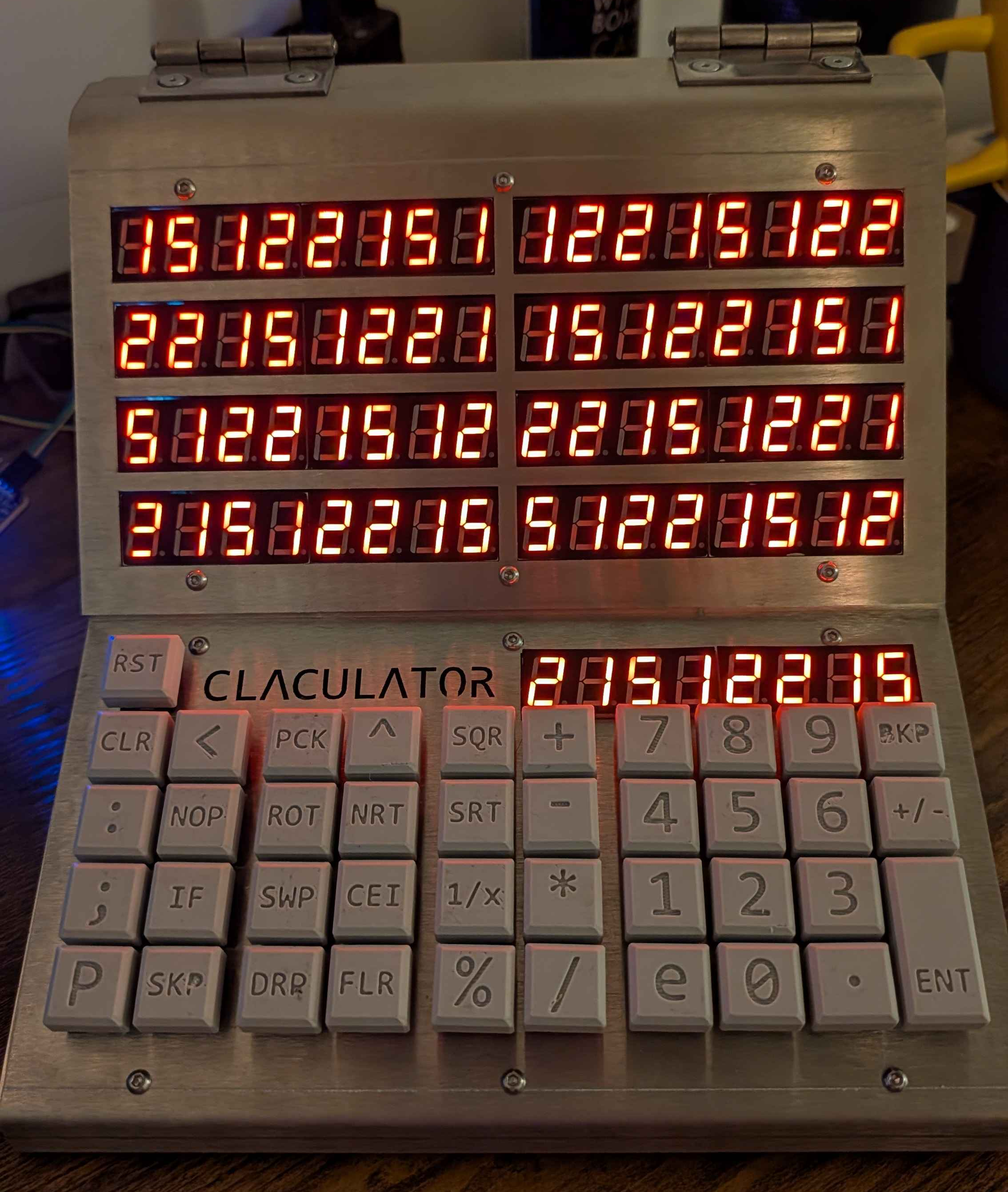
Fully assembled Claculator

Display

The seven-segment display board supports nine numeric displays, each with eight digits. It contains an SRAM chip which interfaces to the rest of the computer as a memory-mapped peripheral. When selected, the address and data bus is connected to the computer to be written to (but not read from) transparently. When the memory is not selected, a counter with a selectable clock source loops through each of the seventy-two digits, reads the corresponding byte from memory, and drives the corresponding digit using one bit for each segement (seven for the numeric part, one for the decimal point) with an array of P- and N-channel MOSFETs.

The front of the display, showing eight numeric displays
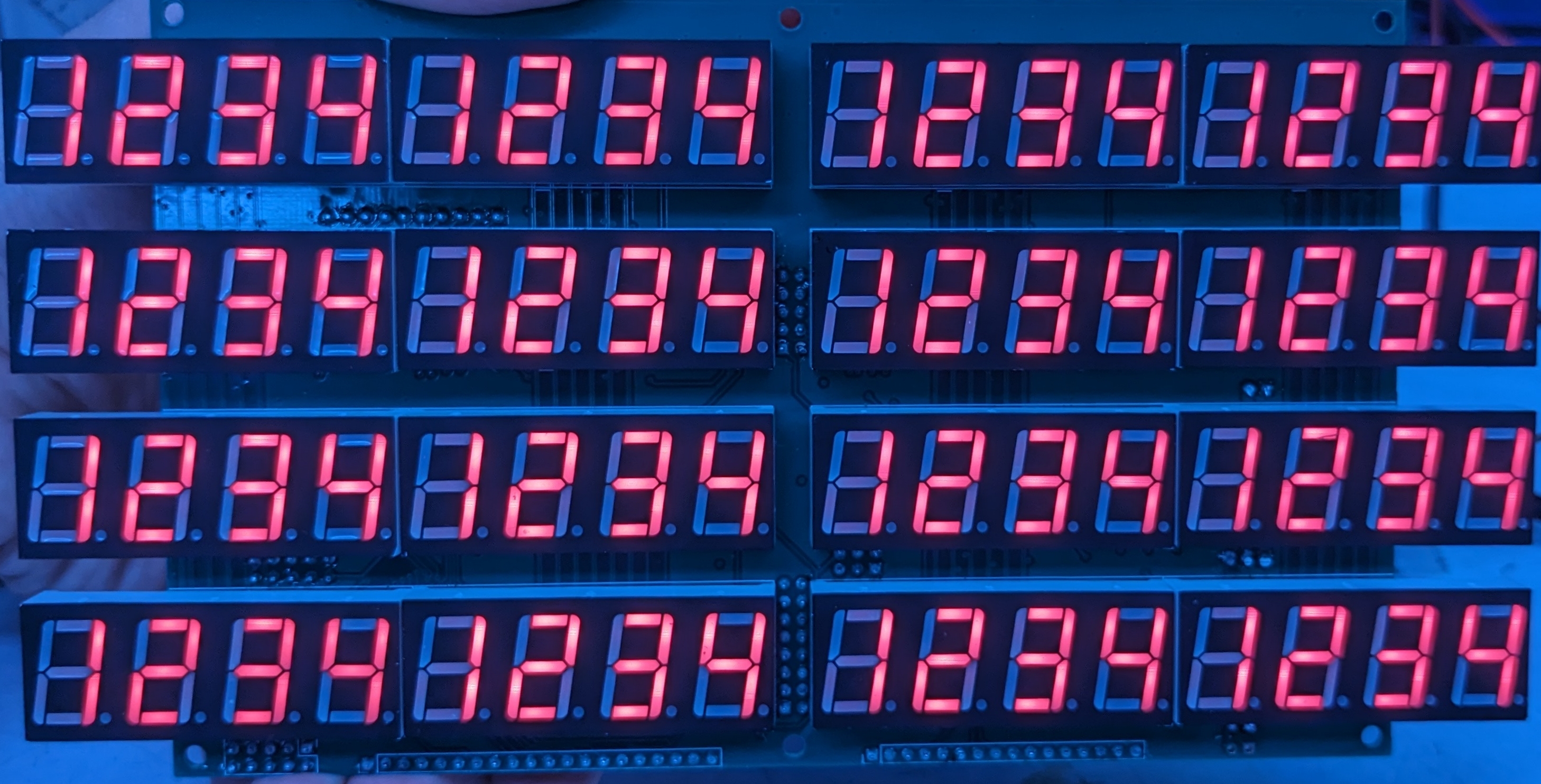
The front of the display, showing eight numeric displays

The back of the display, showing the logic and driver chips
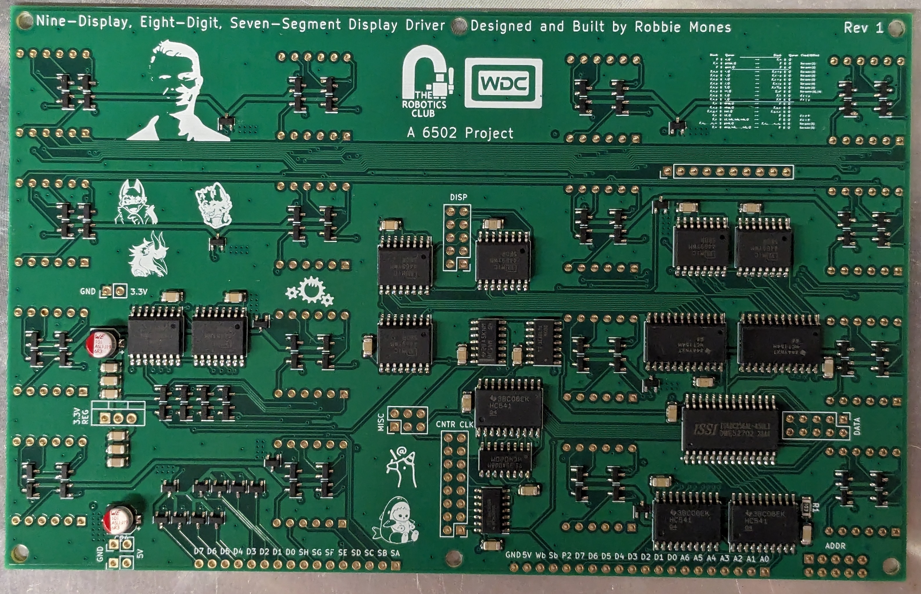
The back of the display, showing the logic and driver chips

Keypad

The keypad input board supports up to sixteen rows (5 are implemented), each with eight buttons. It detects rising edges of each button (equivalent to KeyDown events) with hardware RC debouncing and writes this information to a hardware FIFO buffer which is interfaced directly to the address and data bus of the system and can be configured to send an interrupt on new information in the buffer. It also has a header and location for a seven-segment display (not populated in these photos) as the ninth display that is driven from the display board.

The front of the keypad, showing five groups of eight keys
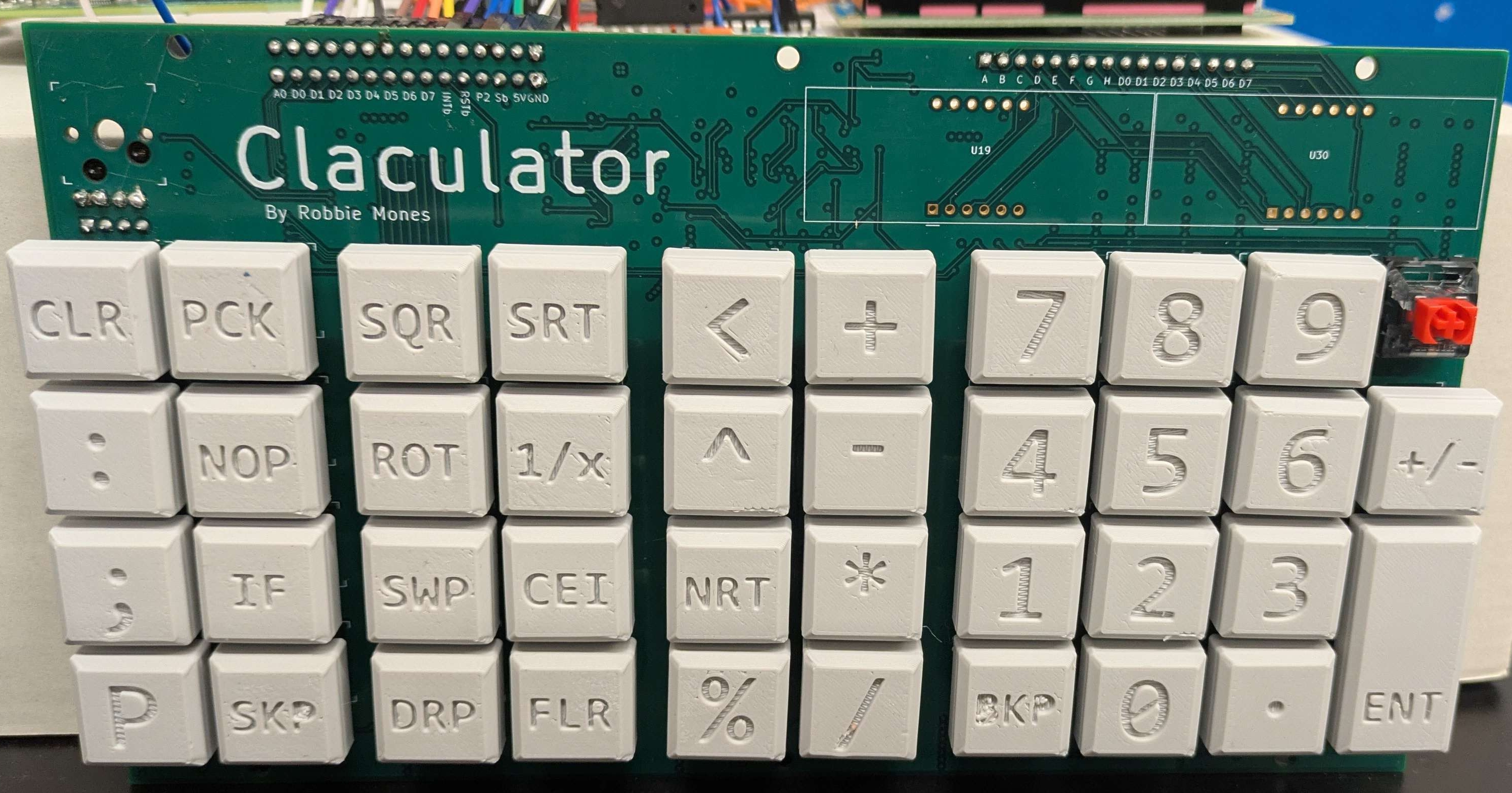
The front of the keypad, showing five groups of eight keys

The back of the keypad, showing the logic chips and hot-swappable key sockets
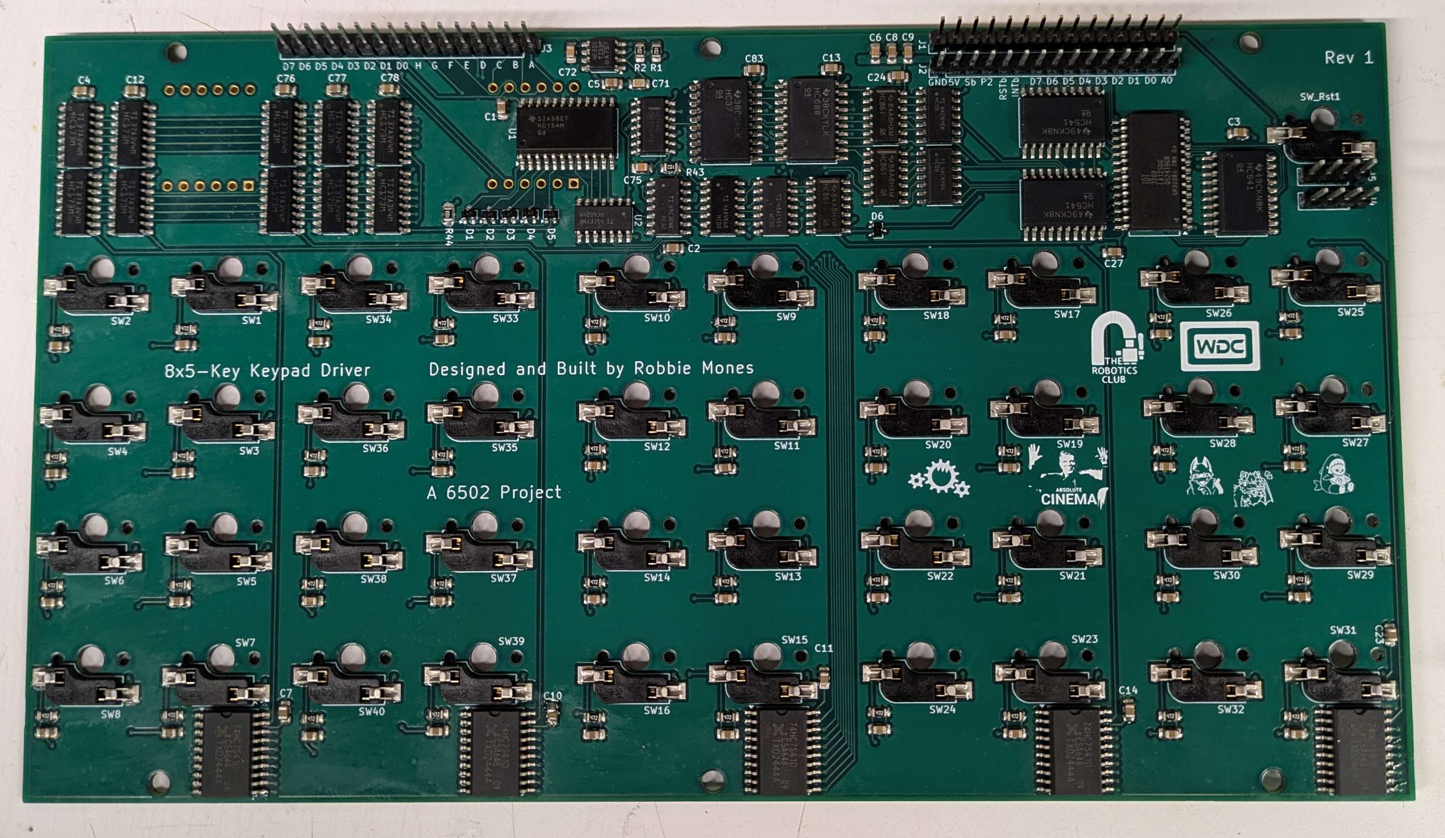
The back of the keypad, showing the logic chips and hot-swappable key sockets

Chassis

The chassis for the Claculator was manufactured by SendCutSend out of 1/8"-thick 304 stainless steel (except for the keypad plate which must be 0.06" thick to fit the keys). It has hinges at the top back to open the Claculator from the front to enable demonstrations and debugging more easily. It is very heavy (8lbs of sheet metal) and was very expensive but it's worth it for the bit.

Model of the assembled Claculator
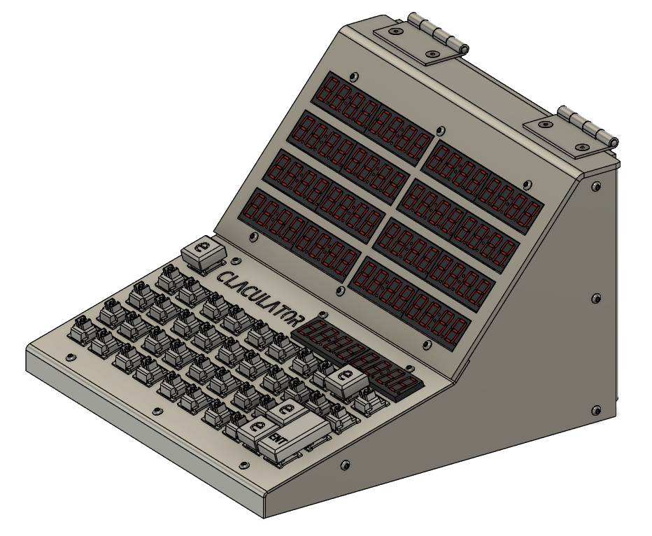
Model of the assembled Claculator

Code

I am currently working on some tests building up to a 32-bit integer mode to develop the RPN behavior and a feature-complete Clac implementation. After this, I will write a software 32-bit floating point implementation to support decimal arithmetic and comparisons. All of the code for this project will be written in 65C02 assembly.

Parts

7
QtyValueFootprintReferences
2CCapacitor_THT:C_Disc_D5.0mm_W2.5mm_P2.50mmC1, C2
2RResistor_THT:R_Axial_DIN0204_L3.6mm_D1.6mm_P5.08mm_HorizontalR1, R2
1Conn_01x06_PinConnector_PinHeader_2.54mm:PinHeader_2x03_P2.54mm_VerticalJ2
1D_ZenerDiode_THT:D_A-405_P7.62mm_HorizontalD1
1NE555PPackage_DIP:DIP-8_W7.62mmU1

Questions

How big is the Clock Addon PCB?

It measures 16.5 × 21.6 mm and has 6 copper layers, 1.6 mm thick.

What parts does the Clock Addon use?

7 parts, built around the NE555P. The full list of its parts is on this page, with links to each part's symbol and footprint where PCBKit's library has them.

Where can I download the Clock Addon KiCad files?

From the Robert-Mones/Claculator repository on GitHub, at the commit this page was made from: the board is Clock_Addon/Clock_Addon.kicad_pcb and its schematic Claculator_Display/Claculator_Display.kicad_sch. PCBKit opens the board in the browser, with nothing to install.

Can I use the Clock Addon design in my own project?

Its repository states no licence, so its author keeps all rights: ask Robert-Mones before reusing the design.

More from Robert-Mones/Claculator

3
  • 6 layers210 × 119 mmClaculator Keypad, the printed circuit board in 3D

    Claculator Keypad

    Robert-Mones/Claculator

    A reverse Polish notation calculator with added features such as comparisons, branching, and custom recursive operators taken from the Clac project from the 15-122 course at Carnegie Mellon University.

    202 parts5
  • 4 layers174 × 109 mmClaculator Display, the printed circuit board in 3D

    Claculator Display

    Robert-Mones/Claculator

    A reverse Polish notation calculator with added features such as comparisons, branching, and custom recursive operators taken from the Clac project from the 15-122 course at Carnegie Mellon University.

    170 parts5
  • 4 layers68.5 × 43.5 mmPunchcard Reader, the printed circuit board in 3D

    Punchcard Reader

    Robert-Mones/Claculator

    A reverse Polish notation calculator with added features such as comparisons, branching, and custom recursive operators taken from the Clac project from the 15-122 course at Carnegie Mellon University.

    36 parts5

Similar boards

  • 2 layers327.9 × 139 mmCoco2, the printed circuit board in 3D

    Coco2

    baldengineer/bit-preserve

    Project for capturing vintage, classic, aka old computer schematics in KiCad.

    147 parts446
  • 2 layers370.8 × 298.5 mm8 Bit Computer, the printed circuit board in 3D

    8 Bit Computer

    The-Invent0r/8-bit-Computer-PCB

    These are the KiCAD files for my 8-Bit Computer.

    323 parts142
  • 2 layers200 × 96 mmTouchtone555, the printed circuit board in 3D

    Touchtone555

    DarcyJProjects/touchtone555

    An open-source DIY, NE555-based analogue synthesizer - play notes with a stylus

    73 parts33
  • 4 layers340 × 210 mmYddraig, the printed circuit board in 3D

    Yddraig

    ddraig68k/hardware

    Schematic and CAD files for my 68K based computer

    224 parts29MIT
  • 2 layers152.9 × 74.9 mmClock, the printed circuit board in 3D

    Clock

    erikvanzijst/clock

    24H digital quartz clock from scratch

    82 parts21
  • 2 layers88.9 × 50.8 mmSynthCard, the printed circuit board in 3D

    SynthCard

    benjiaomodular/SynthCard

    I designed this project with the help of PCBWay. You can get a copy of these cards through the PCBWay Shared Projects page.

    16 parts19MIT
  • 4 layers194.5 × 188.6 mmMyCpu, the printed circuit board in 3D

    MyCpu

    fortinsylvain/MyCpu

    Home brew CPU Hardware with 1-bit ALU implementation using 74LSxx, a micro-code and assembler coded in C#.

    162 parts18MIT
  • 2 layers145.3 × 129.9 mmC128Diag, the printed circuit board in 3D

    C128Diag

    hackup/C128Diag

    Replica of the Commodore C128 Diagnostic Test cartridge Assy No. 325093-01.

    61 parts16