
2 layers103 × 50 mm

 rmingon/step-down-2Amps
Step-down 3.3 V / 2 A buck regulator built in KiCad around TI’s TPS562200, with ready-to-fab outputs.
Step down-2Amps is an open-source printed circuit board by rmingon, from the rmingon/step-down-2Amps repository on GitHub. It is a 2-layer board of 16.5 × 13 mm with 10 parts on 6 nets, routed with 25 tracks and 9 vias.
It is built around the TPS562200DDC. Its parts include 5 capacitors, 2 resistors, 1 IC, 1 connector and 1 inductor. It belongs with the power boards of this library.
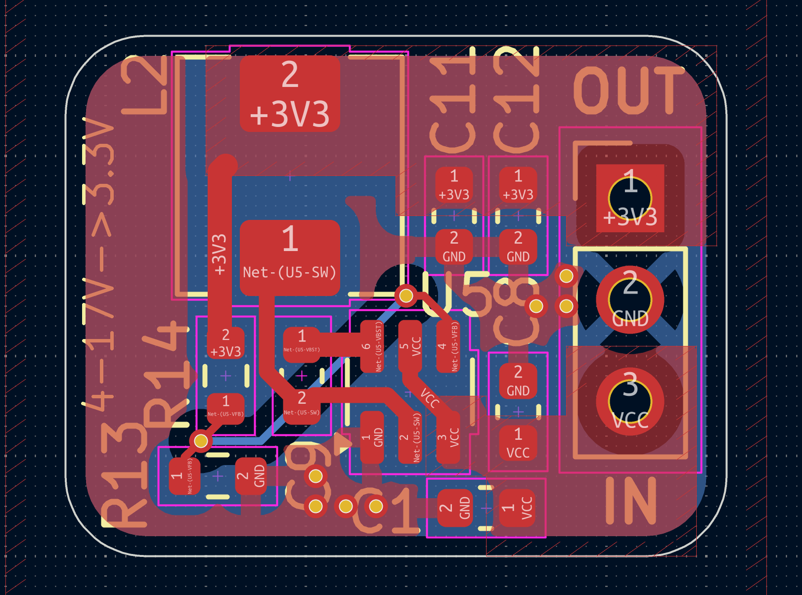
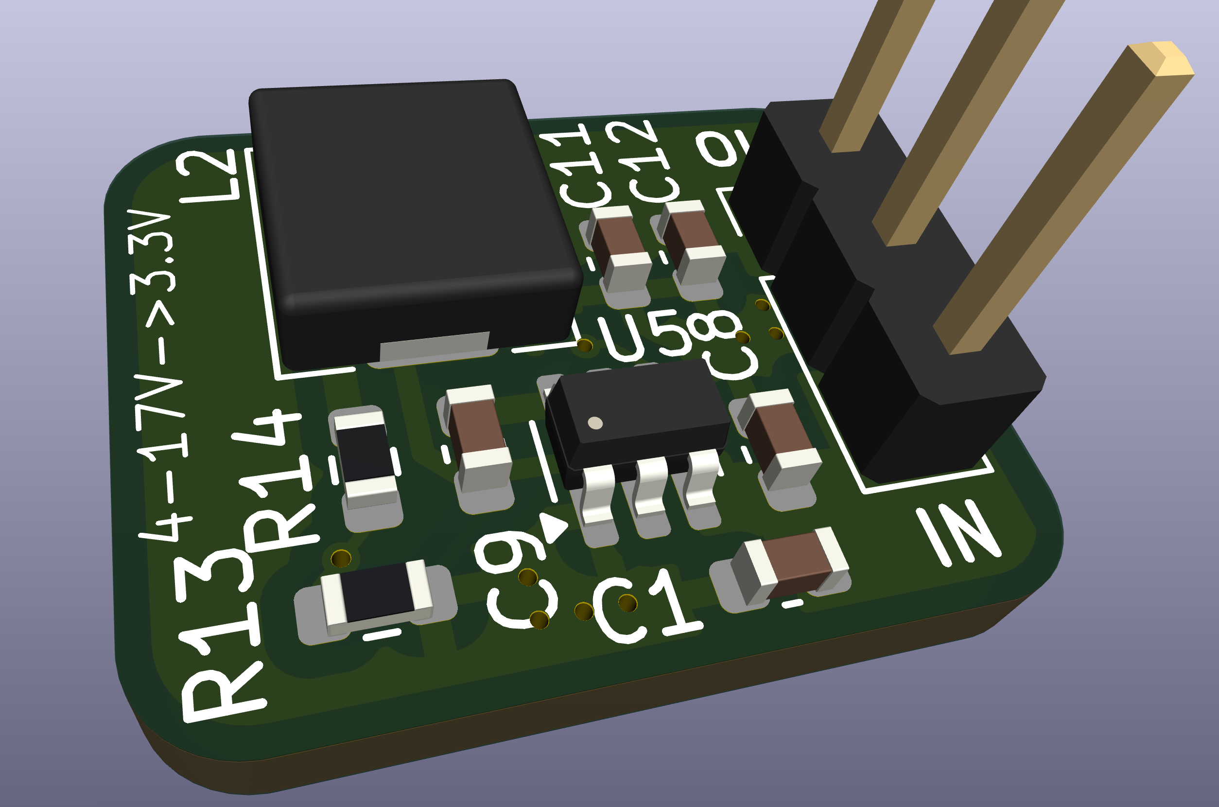
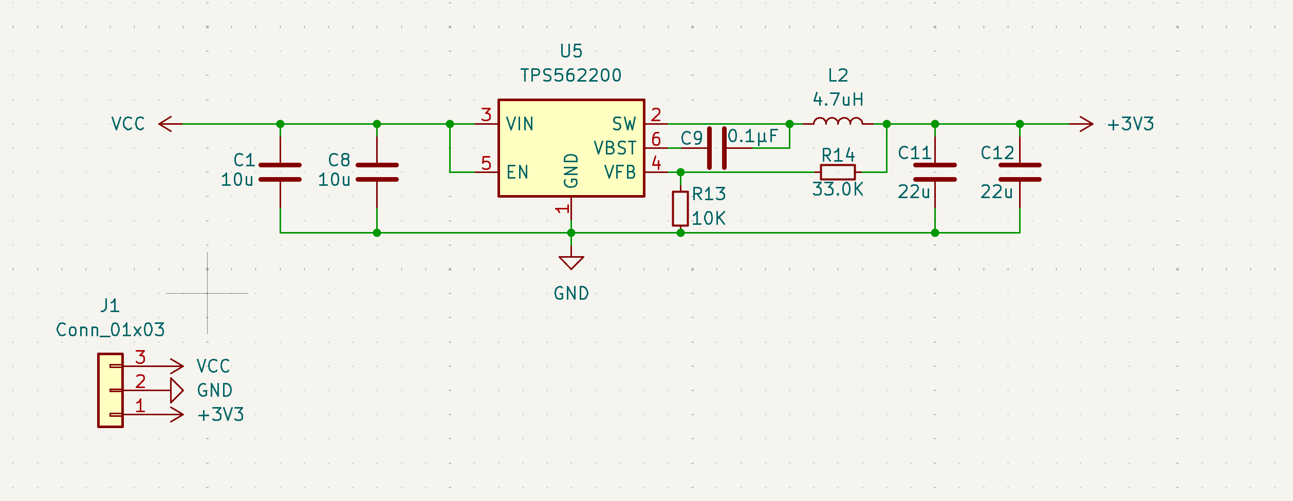
TPS562200, delivering a regulated 3.3 V rail at up to 2 A continuous load.TPS562200 operating range)J1, from silkscreen Pin 1 marker toward Pin 3)| Pin | Net | Function |
|---|---|---|
| 1 | +3V3 | Regulated 3.3 V output |
| 2 | GND | Power ground / return |
| 3 | VCC | Raw input voltage (also feeds EN) |
hardware.kicad_sch, hardware.kicad_pcb: KiCad 8 project files for schematic and board layout.pcb.png, 3d.png, schematic.png: Quick references for the layout, render, and top-level schematic.EN is permanently tied high through the resistor divider, so the regulator starts when VCC is present.C11, C12) for stability; both footprints can be stuffed for additional bulk capacitance.J1.VCC/GND and confirm the 3.3 V output on +3V3.R14 high-side, R13 low-side) per the TPS562200 datasheet (Vout = 0.765 V * (1 + R14 / R13)).CERN-OHL-P v2). See LICENSE for the full terms and obligations when using the design or producing hardware from it.| Qty | Value | Footprint | References |
|---|---|---|---|
| 2 | 10u | Capacitor_SMD:C_0603_1608Metric | C1, C8 |
| 2 | 22u | Capacitor_SMD:C_0603_1608Metric | C11, C12 |
| 1 | 0.1µF | Capacitor_SMD:C_0603_1608Metric | C9 |
| 1 | 10K | Resistor_SMD:R_0603_1608Metric | R13 |
| 1 | 33.0K | Resistor_SMD:R_0603_1608Metric | R14 |
| 1 | 4.7uH | Inductor_SMD:L_Chilisin_BMRA00050520 | L2 |
| 1 | Conn_01x03 | Connector_PinHeader_2.54mm:PinHeader_1x03_P2.54mm_Vertical | J1 |
| 1 | TPS562200 | Package_TO_SOT_SMD:SOT-23-6 | U5 |

rmingon/Falcon-Edge
A 3D-printable flying-wing airframe with a custom ESP32 flight computer—open hardware you can solder, screw together, and fly.

bastian-bou/NixieNTPClock
Nixie clock around ESP32 connected to a NTP server

vatsalbansal123/reaction-wheel-controller-pcb
Open-source FOC motor controller PCB for a reaction wheel — STM32G431 + DRV8311H driving a BLDC motor, with CAN bus interface. Designed in KiCad.

nyuad-space/dumpling
Modular payload for high-speed logging and benchmarking of COTS sensors, enabling real-world performance data and open sharing.


rmingon/PickOMatic-V2
One board to drive your entire pick-and-place machine: RISC-V CH32V317, 7 stepper channels, Ethernet, USB-C, vacuum and lighting control. Open hardware.

rmingon/ScrapHawk
An ultra-budget, high-performance drone flight controller powered by the RP2040. Featuring a full 9-axis navigation stack, GPS, dual-stage power filtering, and a dual-core FreeRTOS architecture.
It measures 16.5 × 13 mm and has 2 copper layers, 1.6 mm thick.
10 parts, built around the TPS562200DDC. The full list of its parts is on this page, with links to each part's symbol and footprint where PCBKit's library has them.
From the rmingon/step-down-2Amps repository on GitHub, at the commit this page was made from: the board is hardware.kicad_pcb and its schematic hardware.kicad_sch. PCBKit opens the board in the browser, with nothing to install.
Its repository states no licence, so its author keeps all rights: ask rmingon before reusing the design.