2 layers100 × 100 mm

 rmingon/digital-clock
Digital clock with atmega and RTC MCP7940 with WS2812b for light
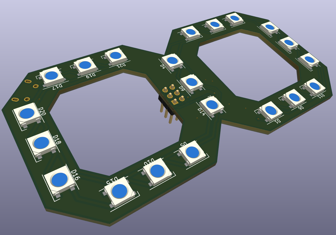
Digital clock is an open-source printed circuit board by rmingon, from the rmingon/digital-clock repository on GitHub. It is a 2-layer board of 50 × 100 mm with 36 parts on 58 nets, routed with 364 tracks and 39 vias.
It is built around the ATMEGA328P-MU, PCF8523T and WS2812B. Its parts include 21 diodes, 4 resistors, 4 connectors, 2 ICs and 2 switches. It belongs with the lEDs and displays boards and the AVR (ATmega, ATtiny) boards of this library.


| Qty | Value | Footprint | References |
|---|---|---|---|
| 21 | WS2812B | LED_SMD:LED_WS2812B_PLCC4_5.0x5.0mm_P3.2mm | D1, D2, D3, D4, D10, D11, D12, D13, D14, D15, D16, D17, D18, D19, D20, D21 +5 |
| 4 | R_Small | Resistor_SMD:R_0603_1608Metric | R1, R2, R3, R4 |
| 2 | Conn_01x04 | Connector_JST:JST_SH_SM04B-SRSS-TB_1x04-1MP_P1.00mm_Horizontal | J3, J4 |
| 2 | SW_SPST | Button_Switch_SMD:SW_SPST_FSMSM | SW1, SW2 |
| 1 | ABS2532768KHZ6T | Crystal:Crystal_SMD_Abracon_ABS25-4Pin_8.0x3.8mm | Y1 |
| 1 | ATmega328P-M | Package_QFP:TQFP-32_7x7mm_P0.8mm | U1 |
| 1 | Battery_Cell | Battery:BatteryHolder_LINX_BAT-HLD-012-SMT | BT1 |
| 1 | C_Small | Capacitor_SMD:C_0603_1608Metric | C1 |
| 1 | Conn_02x03_Odd_Even | Connector_PinHeader_2.54mm:PinHeader_2x03_P2.54mm_Vertical | J2 |
| 1 | PCF8523T | Package_SO:SOIC-8_3.9x4.9mm_P1.27mm | U2 |
| 1 | USB_OTG | Connector_USB:USB_Micro-B_Molex-105017-0001 | J1 |
It measures 50 × 100 mm and has 2 copper layers, 1.6 mm thick.
36 parts, built around the ATMEGA328P-MU, PCF8523T and WS2812B. The full list of its parts is on this page, with links to each part's symbol and footprint where PCBKit's library has them.
From the rmingon/digital-clock repository on GitHub, at the commit this page was made from: the board is digital-clock-pcb/digital-clock.kicad_pcb and its schematic digital-clock-pcb/digital-clock.kicad_sch. PCBKit opens the board in the browser, with nothing to install.
Its repository states no licence, so its author keeps all rights: ask rmingon before reusing the design.

vinnesttree/TixClock
The Tix Clock was originally sold in 2006 by ThinkGeek. Unfortunately, these are no longer sold. This project hopes to try to recreate this iconic clock in a miniature format.

DiFir28/RJS-lightweight-360-IR-ball-sensor
Code for custom IR ball sensors for reglament RJS lightweight


saewoonam/ble_adv_covid
Repo to implement the advertise and scanner portion for bluetooth to enable encounter/exposure tracing (e.g. Apple/Google / TCN / etc...) on a nRF52840 based battery powered dongle/device

diegodemarco/cog1
cog1 is an open-source industrial IoT gateway (hardware and software) built as a motherboard hosting an Orange Pi Zero 3 Linux SBC.

can-caglar/Data-Logger-STM32
The Serial Snooper is a UART data logger with automatic baud rate detection, real-time data stamping and a command-line-interface for configuration, running on an STM32F3 microcontroller.