2 layers40 × 30 mm
Esphome xiao base
0rax/esphome-xiao-base
XIAO base board PCB & configuration for ESPHome based sensors.
10 parts5CERN-OHL-S-2.0
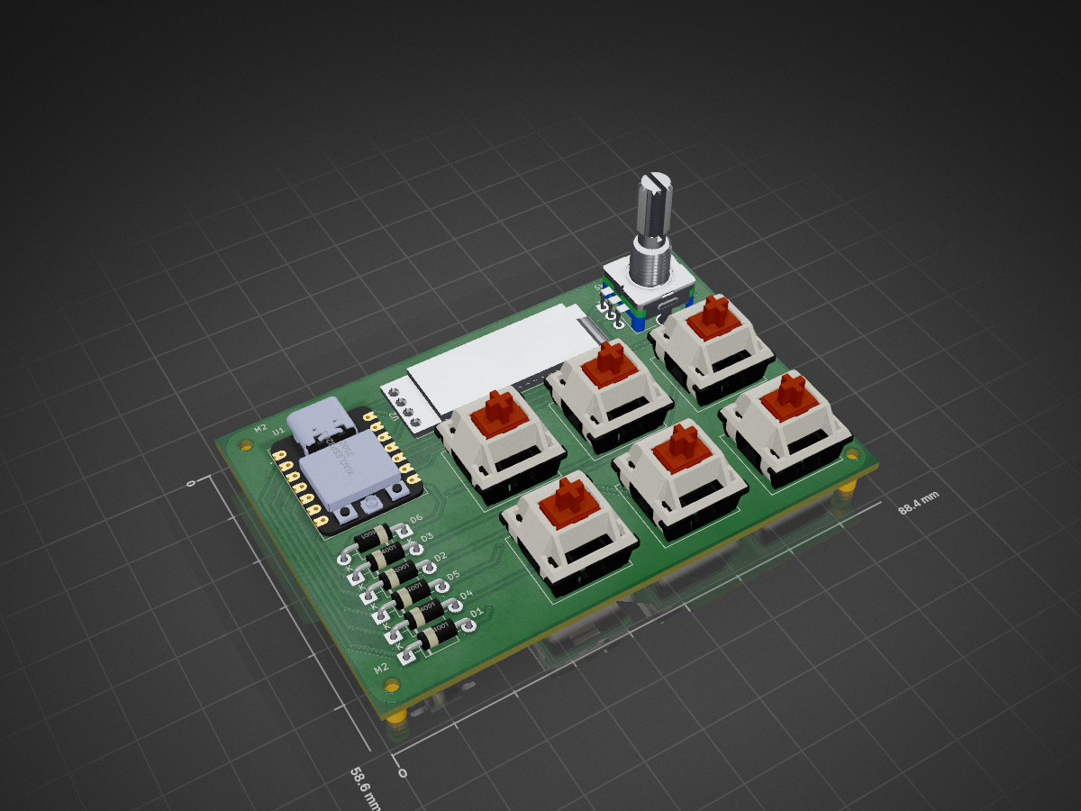
 RishitJain-dev/Hackpad
A small macropad for Hack Club with a OLED display, rotary encoder dial and 6 Keys
Hackpad is an open-source printed circuit board by RishitJain-dev, from the RishitJain-dev/Hackpad repository on GitHub. It is a 2-layer board of 88.4 × 58.6 mm with 18 parts on 20 nets, routed with 83 tracks and 9 vias.
It is built around the XIAO ESP32C3. Its parts include 7 switches, 6 diodes and 2 ICs. It belongs with the keyboards and input and lEDs and displays boards and the ESP32 and RISC-V boards of this library.
A custom 6-key mechanical Macropad with rotary encoder, OLED screen and fully programmable shortcuts for your workflow.
I used Figma to create initial designs before designing the PCB and schematic
-ER_OLEDM0.91_1x-I2C
-RotaryEncoder_Switch_MP
-XIAO_ESP32C3
-Cherry MX Switches
-1N4001 Diode
I used KiCad to design the PCB, routing traces, and linking 3D models to each footprint to create a final 3D render of the PCB
I used Onshape to design the CAD, splitting the casing into 3 pieces, the body, top and bottom, all connected by nuts and bolts, and keycaps for the switches and a knob for the rotary encoder
I built and soldered the macropad in real life after waiting for 3 weeks to get the parts
6x Cherry MX Switches
6x Keycaps any colour (preferably black)
1x EC11 Rotary Encoder with switch and MP pins
1x Seeed XIAO RP2040
4x M3 Nut and Bolt, 2cm, Low profile top
4x M3 Spacers, 3mm diameter, 0.6cm, circular, non-threaded
1 Case (3 printed parts)
| Qty | Value | Footprint | References |
|---|---|---|---|
| 6 | 1N4001 | Diode_THT:D_DO-41_SOD81_P10.16mm_Horizontal | D1, D2, D3, D4, D5, D6 |
| 6 | SW_Push | Button_Switch_Keyboard:SW_Cherry_MX_1.00u_Plate | SW1, SW2, SW3, SW4, SW5, SW7 |
| 3 | MountingHole_2.2mm_M2 | MountingHole:MountingHole_2.2mm_M2 | M2, M2, M2 |
| 1 | ER_OLEDM0.91_1x-I2C | Display:ER_OLEDM0.91_1x-I2C | U2 |
| 1 | RotaryEncoder_Switch_MP | Rotary_Encoder:RotaryEncoder_Alps_EC11E-Switch_Vertical_H20mm_CircularMountingHoles | SW6 |
| 1 | XIAO_ESP32C3 | footprints:MODULE_XIAO_ESP32C3 | U1 |
It measures 88.4 × 58.6 mm and has 2 copper layers, 1.6 mm thick.
18 parts, built around the XIAO ESP32C3. The full list of its parts is on this page, with links to each part's symbol and footprint where PCBKit's library has them.
From the RishitJain-dev/Hackpad repository on GitHub, at the commit this page was made from: the board is PCB/Hackpad.kicad_pcb and its schematic PCB/Hackpad.kicad_sch. PCBKit opens the board in the browser, with nothing to install.
Its repository states no licence, so its author keeps all rights: ask RishitJain-dev before reusing the design.
0rax/esphome-xiao-base
XIAO base board PCB & configuration for ESPHome based sensors.


aayu0-0/SEEED-RS485-Extension-Board-reverse-engineering-project
SEEED RS485 Extension Board reverse-engineering project

AID-IOT/IOT-Memento-Design
A keepsake PCB built at the AICTE IDEA Lab, Poornima College of Engineering. It is a working board as well as a memento: a Seeed XIAO ESP32C3 drives four WS2812B LEDs and reads a BMP280 pressure/temperature sensor, and…
