


2 layers70 × 45 mm

 RincewindWizzard/magic-switchboard18
A magic schwitchboard is a little box with four switches and four lamps colored in red, green, blue and yellow. The switches have got hats in the same colors.
Magic switchboard is an open-source printed circuit board by RincewindWizzard, from the RincewindWizzard/magic-switchboard repository on GitHub, published under the GPL-3.0 licence. It is a 2-layer board of 100 × 62 mm with 26 parts on 20 nets, routed with 135 tracks and 0 vias.
It is built around the ATTINY2313A-PU and BC547. Its parts include 5 resistors, 4 diodes, 4 transistors, 4 switches and 2 connectors. It belongs with the AVR (ATmega, ATtiny) boards of this library.
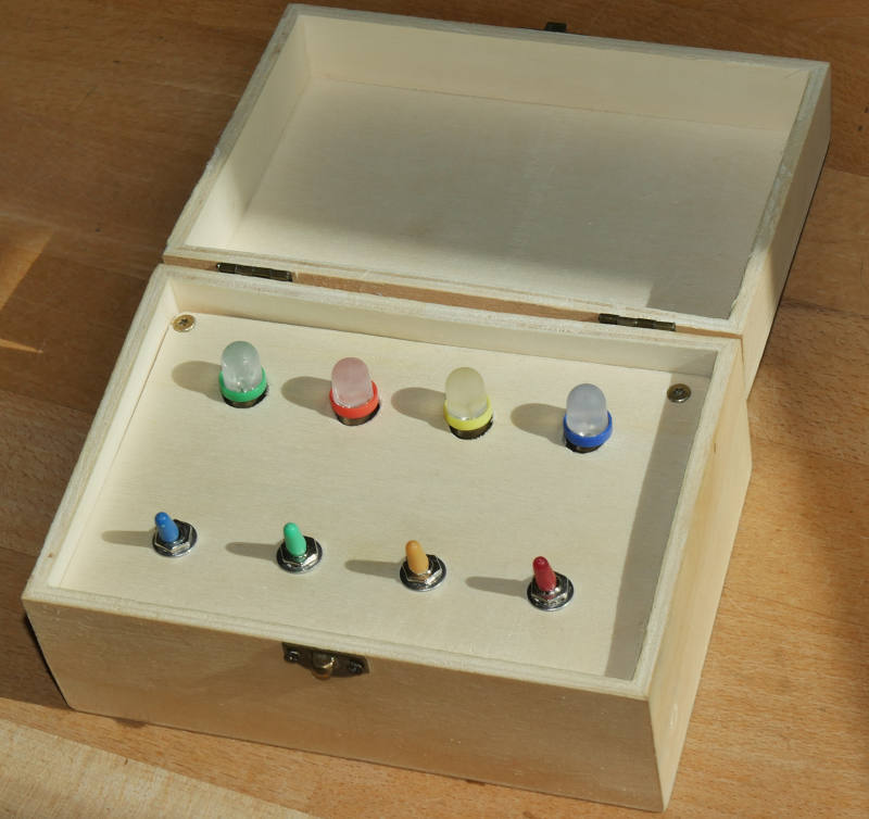
A magic schwitchboard is a little box with four switches and four lamps colored in red, green, blue and yellow. The switches have got hats in the same colors. You can change the position of the lamps and the hats in any way you want. But the red switch always lights the red lamp, the blue the blue, the yellow the yellow and the green the green one. How does this work? The magician is the one operating the switchbox. He has to remember which switch was turned off last. He then hands off the box to the audience and asks them to rearrange the colors. When the audience returns his box he remembers the sequence in which the lights turn on and turns the switches with matching color. For the audience it seems like the colors are connected somehow.
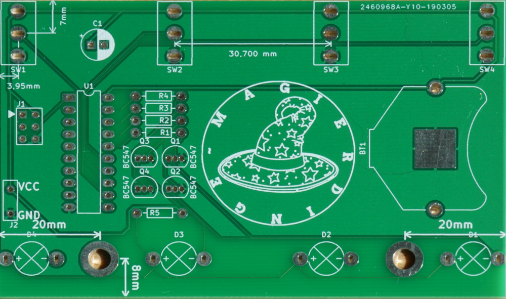
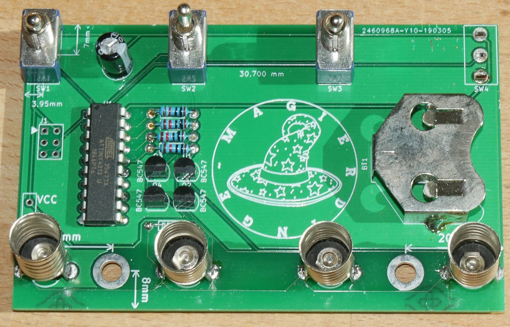
You can find wiring instructions in the Schematics. The Attiny4313A can be powered with up to 5V.
With the BC547 transistor you can safely drive a current up to 100 mA and voltage of 50V for your light bulbs. For bigger loads consider using TIP100.
The voltage source for the arduino nano can be seperate to the voltage source of the lights, but they have to have a common ground (GND) for the circuit to work. For driving 230VAC (common household plug) light bulbs you might want to use a galvanic separation (opto-isolator). If you don't know what that means, don't try it.
If all lamps are off, the ATtiny is switched into sleep mode, which draws significant less current. This circuit doesn't have a low power warning, so if there is strange behaviour (lamps dont turn on as expected) you might try change your batteries.
The sequence in which the lamps turn on is determined by last lever turned off. After a longer sleep time (ca. 2.5sec) it resets to default = 0 lever.
| Lever (left to right) | Turn on Sequence |
|---|---|
| 0 | 0, 1, 2, 3 |
| 1 | 1, 0, 2, 3 |
| 2 | 2, 3, 1, 0 |
| 3 | 3, 2, 1, 0 |
In order to connect the correct colors from levers to lamps, you need to remember which lamp turns on next and flip the lever with the corresponding color.
You find the code here.
| Qty | Value | Footprint | References |
|---|---|---|---|
| 4 | 10k | switchboard:Resistor | R1, R2, R3, R4 |
| 4 | BC547 | switchboard:BC547 | Q1, Q2, Q3, Q4 |
| 4 | MTS-103 | switchboard:MTS-103 Switch | SW1, SW2, SW3, SW4 |
| 4 | Red | switchboard:E10 Edison Socket Print Pins | D1, D2, D3, D4 |
| 2 | LOGO | switchboard:Siegelstempel | G***, G*** |
| 2 | M4 | MountingHole:MountingHole_4.3mm_M4_DIN965_Pad | , |
| 1 | 100uF | switchboard:CP_Radial_D6.3mm_P2.50mm | C1 |
| 1 | 3V | switchboard:BatteryHolder_Keystone_3009_1x2450 | BT1 |
| 1 | 5V max | switchboard:ScrewTerminal1x2 | J2 |
| 1 | ATtiny2313A-PU | switchboard:ATtiny2313 | U1 |
| 1 | AVR-ISP-6 | switchboard:ISP6 | J1 |
| 1 | LED_brightness | switchboard:Resistor | R5 |
It measures 100 × 62 mm and has 2 copper layers, 1.6 mm thick.
26 parts, built around the ATTINY2313A-PU and BC547. The full list of its parts is on this page, with links to each part's symbol and footprint where PCBKit's library has them.
From the RincewindWizzard/magic-switchboard repository on GitHub, at the commit this page was made from: the board is kicad/magic-switchboard/magic-switchboard.kicad_pcb. PCBKit opens the board in the browser, with nothing to install.
Its repository publishes it under the GPL-3.0 licence: you may reuse it on that licence's terms (keep the author's notice, and for a copyleft licence share your changes alike).


GrzegorzewskiSzymon/Controlled-UV-lamp-for-making-PCBs
This project is originally written for ATtiny2313A with external 16MHz oscilator.

mafdezmoreno/ATtiny2313_Clock_MikroC
DIY Clock. Code. PCB (KiCAD). 3D STL


ondras12345/pm-sensor
SPS30-based PM2.5 particulate matter sensor with RS485
