2 layers94 × 87.6 mm
CNC relays
ondras12345/CNC
My CNC 1610 and Stepcraft model 600 configuration and CNC-related notes
100 partsMIT

 ondras12345/pm-sensor
SPS30-based PM2.5 particulate matter sensor with RS485
Pm sensor UART is an open-source printed circuit board by ondras12345, from the ondras12345/pm-sensor repository on GitHub, published under the MIT licence. It is a 2-layer board of 49.5 × 59.7 mm with 38 parts on 38 nets, routed with 244 tracks and 8 vias.
It is built around the ATTINY2313A-PU, THVD1400DRL and AZ1117H-3.3TRE1, with the 0ZCF0150FF2C, 54601-908WPLF and SM712-02HTG among its other parts. Its parts include 11 capacitors, 6 resistors, 4 ICs, 4 connectors and 2 diodes. It belongs with the interfaces and adapters and sensors and measurement boards and the AVR (ATmega, ATtiny) boards of this library.


An SPS30-based outdoor particulate matter sensor for Home Assistant.
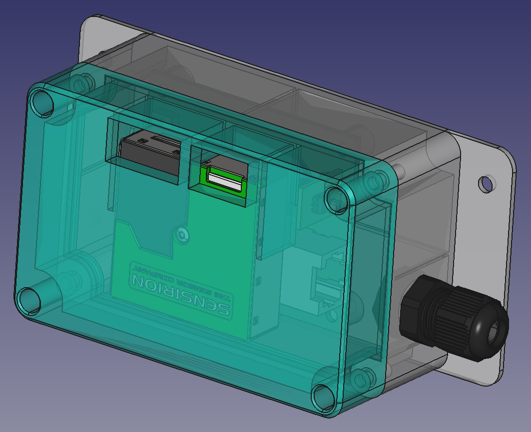
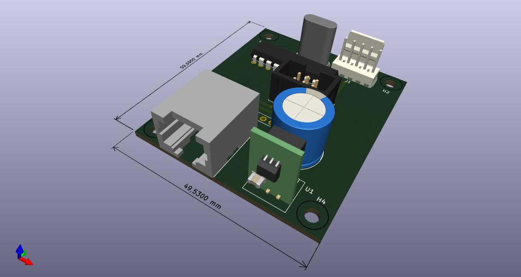
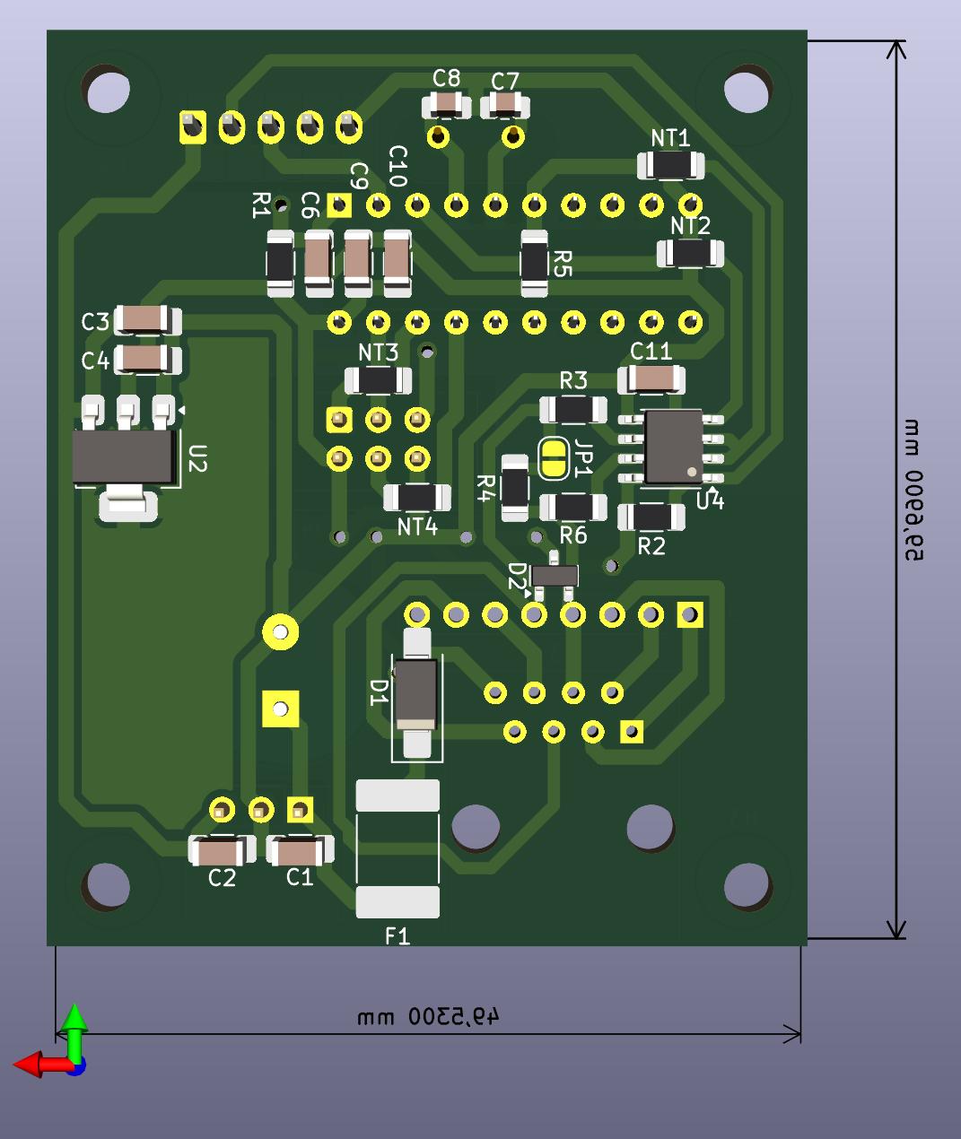
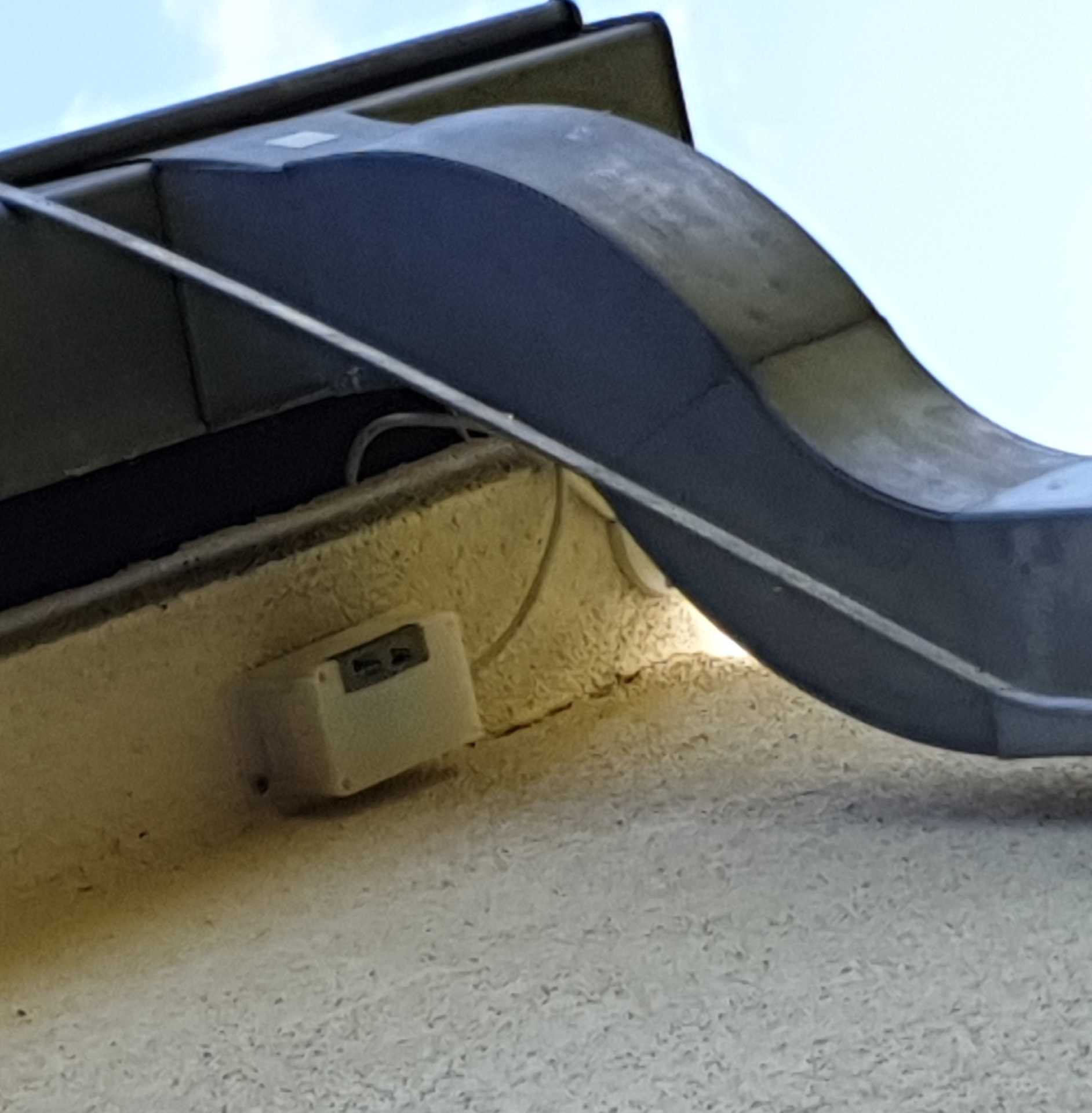
This repository contains hardware designs and firmware for a PCB that connects to the UART interface on an SPS-30 sensor and allows it to be used via a half-duplex RS-485 link. It is designed to be put in one enclosure with the sensor and receive both power and commands via a standard UTP cable with RJ-45 connectors (but it does not use Ethernet).
The PCB is populated with a switch mode power supply module, an RS-485 transceiver and an ATtiny2313 microcontroller. The data out pin of the transceiver is connected straight to the SPS-30's Rx pin, the SPS-30's Tx pin is connected to the Rx pin of the MCU, and the MCU's Tx is connected to the transceivers data input.
In normal mode, the transceiver is put in receive mode, and the remote master is free to send any commands to the sensor. When the sensor sends a response, the bytes are buffered in the MCU. The MCU then switches the transceiver to transmit mode and empties its buffer. Finally, the normal (receive) mode is restored, and the device is ready to receive the next command from the master.
The Sensirion UART protocol is half-duplex in nature, so the use of a half-duplex physical link should not introduce any issues.
The software directory contains a program that makes a Linux
server with a USB to RS485 converter to talk to the sensor and periodically
publish readings to an MQTT topic, where they can be picked up by Home
Assistant.
0x7E start/stop byte
| Qty | Value | Footprint | References |
|---|---|---|---|
| 4 | MountingHole | MountingHole:MountingHole_3.2mm_M3 | H1, H2, H3, H4 |
| 4 | NetTie_2 | Resistor_SMD:R_1206_3216Metric_Pad1.30x1.75mm_HandSolder | NT1, NT2, NT3, NT4 |
| 3 | 100n | Capacitor_SMD:C_1206_3216Metric_Pad1.33x1.80mm_HandSolder | C6, C9, C11 |
| 3 | 10k | Resistor_SMD:R_1206_3216Metric_Pad1.30x1.75mm_HandSolder | R1, R2, R5 |
| 2 | 10 | Resistor_SMD:R_1206_3216Metric_Pad1.30x1.75mm_HandSolder | R3, R6 |
| 2 | 18p | Capacitor_SMD:C_0805_2012Metric_Pad1.18x1.45mm_HandSolder | C7, C8 |
| 2 | 22u / 10V | Capacitor_SMD:C_1206_3216Metric_Pad1.33x1.80mm_HandSolder | C2, C4 |
| 1 | 0ZCF0150FF2C | Fuse:Fuse_2920_7451Metric_Pad2.10x5.45mm_HandSolder | F1 |
| 1 | 10u / 10V | Capacitor_SMD:C_1206_3216Metric_Pad1.33x1.80mm_HandSolder | C3 |
| 1 | 10u / 50V | Capacitor_SMD:C_1206_3216Metric_Pad1.33x1.80mm_HandSolder | C1 |
| 1 | 120 / 0.25W | Resistor_SMD:R_1206_3216Metric_Pad1.30x1.75mm_HandSolder | R4 |
| 1 | 1u | Capacitor_SMD:C_1206_3216Metric_Pad1.33x1.80mm_HandSolder | C10 |
| 1 | 3.6864M-49S-SR | Crystal:Crystal_HC49-U_Vertical | Y1 |
| 1 | 54601-908WPLF | ondra:RJ45_54601-908WPLF | J3 |
| 1 | ATTINY2313A-PU | Package_DIP:DIP-20_W7.62mm | U3 |
| 1 | AVR-ISP-6 | Connector_IDC:IDC-Header_2x03_P2.54mm_Vertical | J4 |
| 1 | AZ1117H-3.3TRE1 | Package_TO_SOT_SMD:SOT-223-3_TabPin2 | U2 |
| 1 | Conn_01x08_Pin | Connector_PinHeader_2.54mm:PinHeader_1x08_P2.54mm_Vertical | J2 |
| 1 | N7805-1PV | ondra:N78xx-xPV | U1 |
| 1 | NS25-W5P | Connector_Molex:Molex_KK-254_AE-6410-05A_1x05_P2.54mm_Vertical | J1 |
| 1 | RAD 1000/50 RM5 SK | Capacitor_THT:CP_Radial_D13.0mm_P5.00mm | C5 |
| 1 | SM712-02HTG | Package_TO_SOT_SMD:SOT-23 | D2 |
| 1 | SMAJ28A-13-F | Diode_SMD:D_SMA_Handsoldering | D1 |
| 1 | SolderJumper_2_Bridged | Jumper:SolderJumper-2_P1.3mm_Bridged_RoundedPad1.0x1.5mm | JP1 |
| 1 | THVD1400DR | Package_SO:SOIC-8_3.9x4.9mm_P1.27mm | U4 |
It measures 49.5 × 59.7 mm and has 2 copper layers, 1.6 mm thick.
38 parts, built around the ATTINY2313A-PU, THVD1400DRL, AZ1117H-3.3TRE1 and 0ZCF0150FF2C. The full list of its parts is on this page, with links to each part's symbol and footprint where PCBKit's library has them.
From the ondras12345/pm-sensor repository on GitHub, at the commit this page was made from: the board is hardware/pm-sensor-UART/pm-sensor-UART.kicad_pcb and its schematic hardware/pm-sensor-UART/pm-sensor-UART.kicad_sch. PCBKit opens the board in the browser, with nothing to install.
Its repository publishes it under the MIT licence: you may reuse it on that licence's terms (keep the author's notice, and for a copyleft licence share your changes alike).
ondras12345/CNC
My CNC 1610 and Stepcraft model 600 configuration and CNC-related notes

ondras12345/vetrnik
Electronics for heating water with power from a 2 kW wind turbine

ondras12345/multicdc
RP2040-based 6-channel USB to UART converter with Zephyr RTOS

printsmith/keyboards
Custom keyboard featuring a modified Southpaw 1800 layout with 2 nav clusters, LCD display and rotary encoders.


punkfab/pcb-corpus
235 real KiCad boards from open-source hardware repositories, prepared as a placement and routing benchmark


ademuri/colordance-circle
An art project that uses arrays of colored lights around a circle to create kaleidoscopic colored shadows.