
2 layers88.9 × 19.2 mm
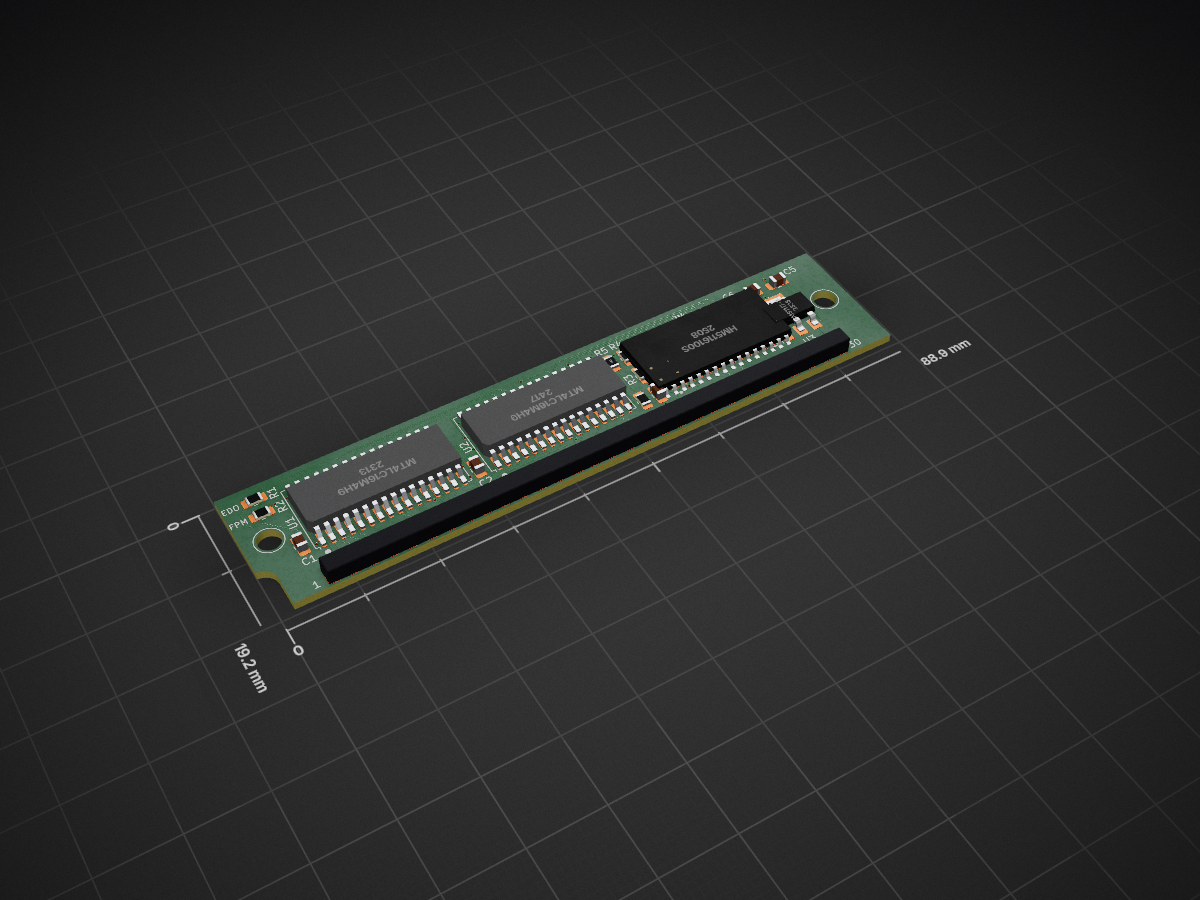
 rigred/SIMMBA-1667
A 16MB 30 pin SIMM
16MB SIPPM 30 rev B1 is an open-source printed circuit board by rigred, from the rigred/SIMMBA-16 repository on GitHub, published under the MIT licence. It is a 4-layer board of 88.9 × 19.2 mm with 17 parts on 51 nets, routed with 804 tracks and 49 vias.
It is built around the AMS1117-3.3. Its parts include 6 resistors, 5 capacitors, 4 ICs and 1 connector.
Open-source 30 pins 16MB SIMM memory module
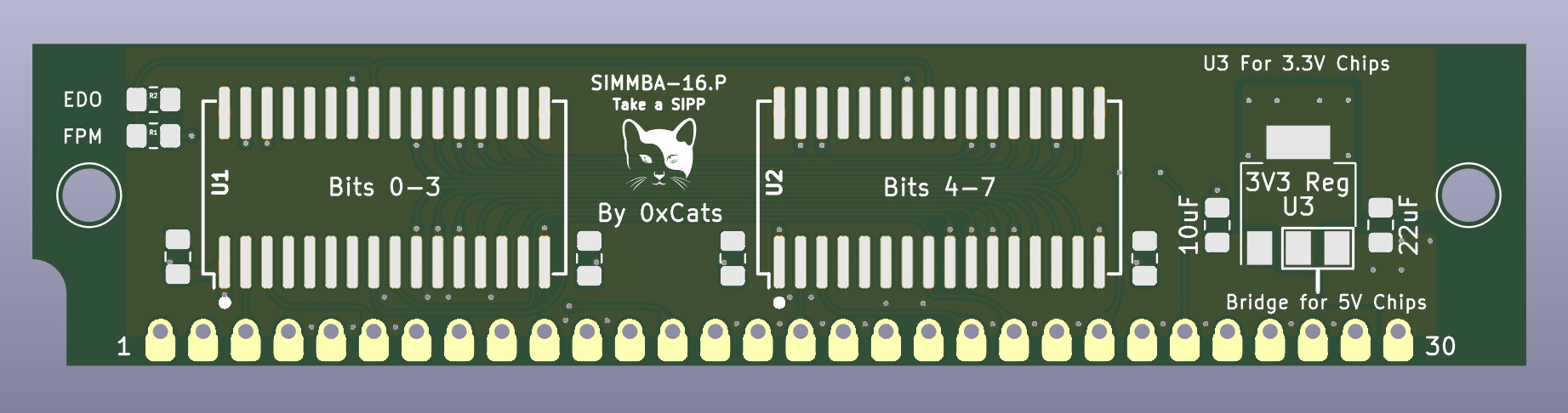
Because I have a 486 motherboard that I'm quite fond of that featured a mix of 2x72pin and 4x30pin SIMM sockets. I wanted to use both at maximum capacity. Also 30 pin SIMM memory prices are not great.
A 16MB(the absolute limit) 30 pin SIMM/SIPP Memory module for various PC compatibles. This board was designed to be as low cost and simple as possible and supports flexibility in ram chip and socket selection.
3.3V chips may be relatively easily found from cheaply available 256MB EDO DIMM's.
These are by far the preferred choice in comparison to the now rarer 5V chips.
I have tested and validated some of the below chips and found them to be 5V IO tolerant in use despite manufacturer data sheets not directly ascribing such.
Of these the Micron chips are by far the most common and robust. All others have been data sheet checked to be electrically compatible.
If you are not using new-old-stock chips and are instead salvaging compatible chips form DRAM Modules then I recommend you take the utmost care in desoldering such.
For the most part only the FPM bridge should be populated. In this mode the CAS signal is tied to the Output Enable signal pin of the chips. On EDO DRAM chips this forces the output buffers to become invalid and cleared as soon as the CAS is toggled and allows EDO chips to behave like FPM chips. In rare cases you may want to configure this module as EDO mode, such as in use with 72pin to 4x30pin SIMM-Saver/SIMM-Expander boards.
If you wish to use these as SIPP modules, in case say your SIMM sockets are broken, or you've found some very obscure motherboard that both supports SIPP memory and this size of module. Then you can simply solder a right angle 100mil/2.54mm header to the holes along the edge.
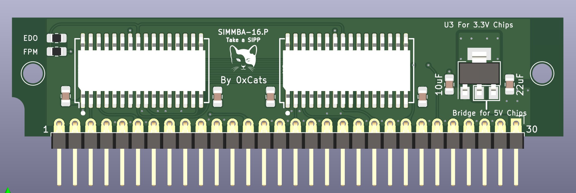
After assembly it is recommended to first power test and check your handiwork in expectation of failure. Feel for any hot parts on the DRAM
If you are getting memory errors there is a good chance that either some pins are not making good contact or you've overheated one of the chips.
Mixing and matching these modules with other modules in the same bank is NOT supported nor recommended.
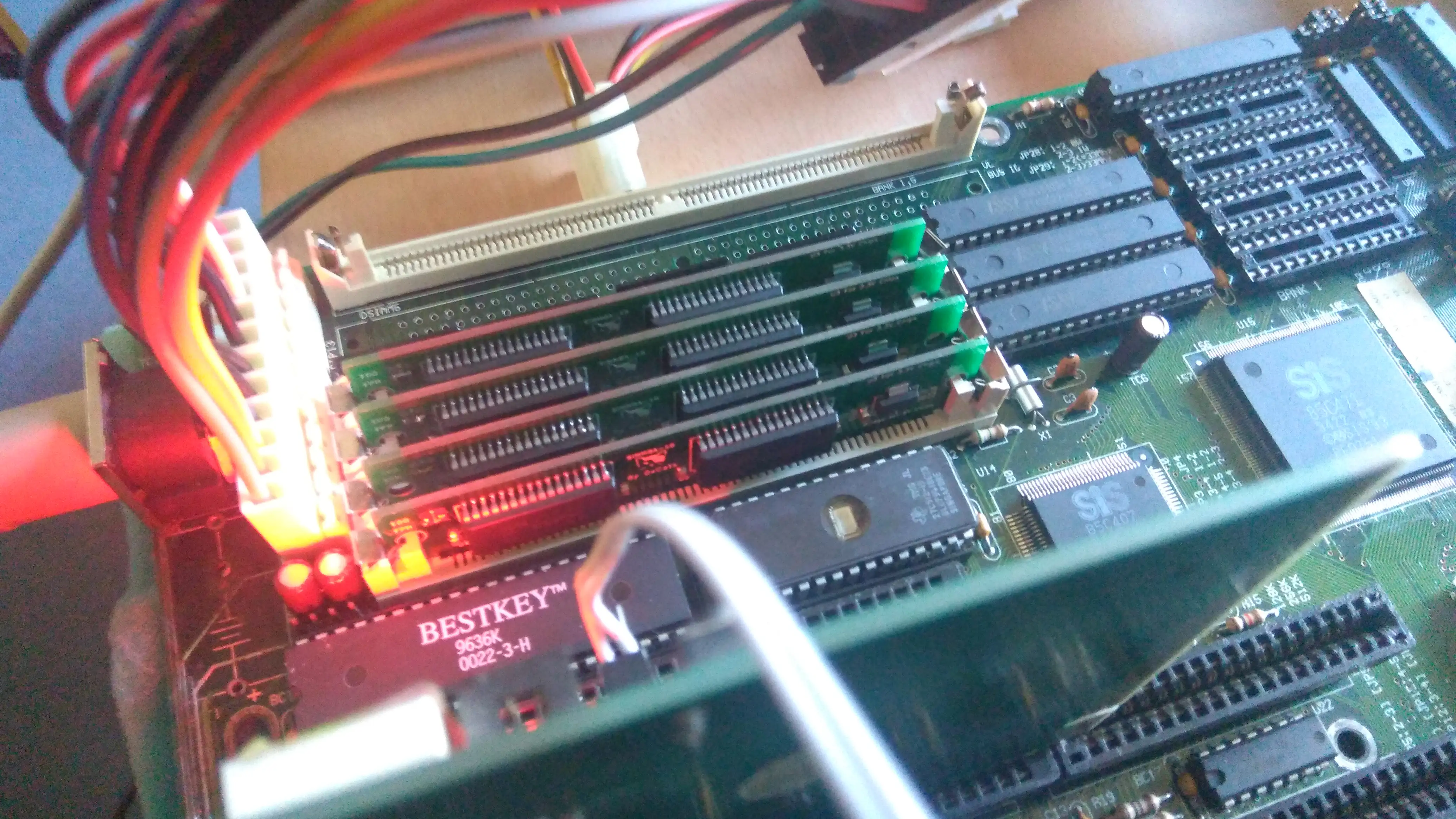
The A1 revision SIMMBA module assembled
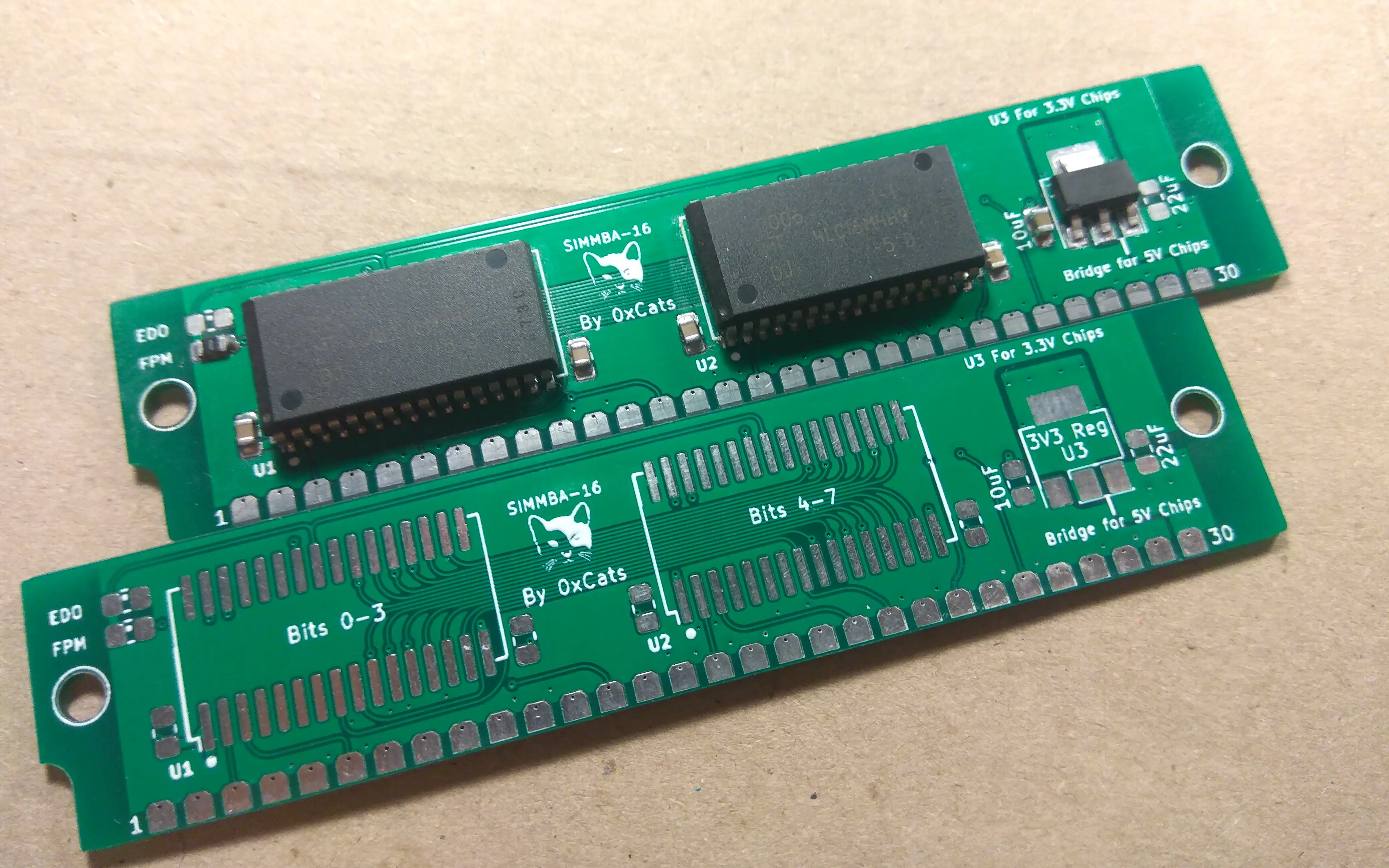
64MB of SIMMBA A1 revision under test
| Qty | Value | Footprint | References |
|---|---|---|---|
| 3 | 0 | Resistor_SMD:R_0805_2012Metric_Pad1.20x1.40mm_HandSolder | R3, R4, R6 |
| 3 | 220nF | Capacitor_SMD:C_0805_2012Metric_Pad1.18x1.45mm_HandSolder | C1, C2, C3 |
| 2 | MT4LC16M4H9 | dram:SOJ-32_10.16x21.50mm_P1.27mm | U1, U2 |
| 1 | 10K | Resistor_SMD:R_0805_2012Metric_Pad1.20x1.40mm_HandSolder | R5 |
| 1 | 10uF | Capacitor_SMD:C_0805_2012Metric_Pad1.18x1.45mm_HandSolder | C6 |
| 1 | 22uF | Capacitor_SMD:C_0805_2012Metric_Pad1.18x1.45mm_HandSolder | C5 |
| 1 | AMS1117-3.3 | Package_TO_SOT_SMD:SOT-223-3_TabPin2 | U3 |
| 1 | EDO | Resistor_SMD:R_0805_2012Metric_Pad1.20x1.40mm_HandSolder | R2 |
| 1 | FPM | Resistor_SMD:R_0805_2012Metric_Pad1.20x1.40mm_HandSolder | R1 |
| 1 | HM5116100S | packageS_SOJ:SOJ-26_300mil | U4 |
| 1 | LOGO | graphics:cat face | G*** |
| 1 | SIMM-30 | edge connectors:SIPP_30_A2 | J1 |


pascallanger/DIY-Multiprotocol-TX-Module
Multiprotocol TX Module (or MULTI-Module) is a 2.4GHz transmitter module which controls many different receivers and models.

fossasia/pslab-hardware
PSLab Hardware Design and Schematics https://pslab.io


MaltWhiskey/Mega-Cube
16x16x16 PL9823 Cube with Teensy 4.0 and FlexIO driver


shamansystems/Cheap-FOCer-2
Low-Cost Motor Controller based on the VESC 6
It measures 88.9 × 19.2 mm and has 4 copper layers, 1.2 mm thick.
17 parts, built around the AMS1117-3.3. The full list of its parts is on this page, with links to each part's symbol and footprint where PCBKit's library has them.
From the rigred/SIMMBA-16 repository on GitHub, at the commit this page was made from: the board is Kicad/Revision B1 Parity/16MB SIPPM 30 rev B1.kicad_pcb and its schematic Kicad/Revision A1 rounded/16MB SIMM 30-rounded.kicad_sch. PCBKit opens the board in the browser, with nothing to install.
Its repository publishes it under the MIT licence: you may reuse it on that licence's terms (keep the author's notice, and for a copyleft licence share your changes alike).