2 layers76 × 50 mm

 rickcox/Hexa-Pi
6 Compute Module Cluster
Hexa Pi 1.1 is an open-source printed circuit board by rickcox, from the rickcox/Hexa-Pi repository on GitHub, published under the CC-BY-4.0 licence. It is a 4-layer board of 150 × 150 mm with 459 parts on 1,108 nets, routed with 6,337 tracks and 2,000 vias.
It is built around the 74LVC1G07SE-7-MS, TPS564201DDC and AP62300TWU, with the FSUSB42MUX, BESDU0603-05 and DMP3013SFV-7(ES) among its other parts. Its parts include 151 capacitors, 117 resistors, 30 ICs, 22 connectors and 13 diodes. It belongs with the Raspberry Pi (Linux) boards of this library.


A small "Front Panel" for the compute modules in the Hexa-Pi PCB. 5 of the modules have no other peripherals other than ethernet.
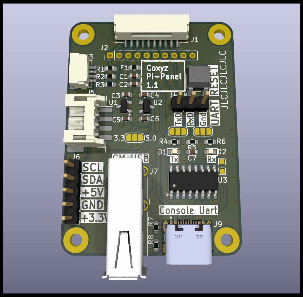
This is a small 36mm X 50mm PCB based that connects to the main Hexa-Pi board using a 10 wire interface with JST connectors.
Since the individual Compute Modules on the main PCB are all powered together, the goal with this board is to allow some basic repair and diagnosis if here are errors or failures on specific modules - without powering the main board down and disassembling the case!
The Activity LED for each module is adjacent and to the left of that board's conncetor. The panel provides for each module individually:
The connection to the main Hexa-Pi board uses a 10 pin JST GH 1.25mm connector.
Manufacturer partnumber SM10B-GHS-TB. It is possible to buy pre-assembeled cables
with this mating connector. They can be purchased with connectors on both ends, or
having 1 end free. Look for something like "GH 1.25MM 10P Single Ended" or "Double Ended".
There are solderable holes on the Pi-Panel so the "Single Ended" type cable assemblies can be used,
and hand soldered on the Pi-Panel end.
Oh, and one ugly secret! The 10 pin JST connectors used between the Panel and main Hexa-Pi
board do not support any type of sequencing (Connect ground before anything else).
As a result, plugging the Pi-Panel into a running Hexa-Pi MAY result in the
connected Compute Module spontaneously resetting. Being careful to have the Panel
grounded before plugging it in seems to minimize this anomaly!
If another version of this board is done, this is on the list of things to try and fix,
but you need to live with it for now.
This was developed in KiCad, and the design files are here. The initial PCB's were built by JLCPCB, and partially assembled by them. The through-hole parts and I2C connectors were hand assembled.
This PCB was small enough, that a panel of 2 was actually build. Directory production has the 1 instance manufacturing data, and directory production-pnl has the 2 instance manufacturing data. At JLCPCB, both PCB's cost the same, since they are under 50mmX50mm. The assembled 2 instance panel costs slightly more due to the incremental cost of the parts - but you get 2 boards for the price of 1!
This work is licensed under the Creative Commons Attribution 4.0 International License. To view a copy of the license, visit https://creativecommons.org/licenses/by/4.0/
| Qty | Value | Footprint | References |
|---|---|---|---|
| 108 | 100n | Capacitor_SMD:C_0402_1005Metric | C10, C11, C100, C101, C102, C103, C104, C105, C106, C107, C108, C113, C115, C117, C122, C124 +92 |
| 23 | SY_IN | TestPoint:TestPoint_Pad_D1.0mm | TP1, TP2, TP3, TP4, TP10, TP11, TP12, TP20, TP22, TP24, TP27, TP28, TP29, TP45, TP47, TP49 +7 |
| 17 | 4K7 DNP | Resistor_SMD:R_0603_1608Metric_Pad0.98x0.95mm_HandSolder | R31, R32, R33, R34, R35, R37, R40, R41, R42, R53, R54, R57, R58, R62, R63, R64 +1 |
| 16 | 1K2 | Resistor_SMD:R_0603_1608Metric | R1, R2, R3, R4, R5, R6, R19, R20, R21, R52, R59, R74, R76, R94, R110, R111 |
| 14 | 10K | Resistor_SMD:R_0603_1608Metric | R7, R8, R9, R10, R11, R12, R13, R14, R24, R25, R66, R67, R78, R79 |
| 12 | HRS_DF40HC_3.0_-100DS-0.4V_58 | CM4IO:HRS_DF40HC(3.0)-100DS-0.4V | ZZ0, ZZ1, ZZ2, ZZ3, ZZ4, ZZ5, ZZ6, ZZ7, ZZ8, ZZ9, ZZ10, ZZ11 |
| 12 | TestPoint | TestPoint:TestPoint_Pad_D1.0mm | TP30, TP31, TP32, TP33, TP34, TP35, TP36, TP37, TP38, TP39, TP40, TP41 |
| 10 | 22K | Resistor_SMD:R_0603_1608Metric | R17, R18, R28, R29, R70, R71, R82, R83, R87, R96 |
| 9 | 10u 25V | Capacitor_SMD:C_0805_2012Metric | C1, C3, C12, C14, C98, C99, C114, C116, C135 |
| 9 | Conn_01x02 | Connector_PinHeader_2.00mm:PinHeader_1x02_P2.00mm_Vertical | J7, J8, J9, J10, J14, J15, J16, J17, J18 |
| 8 | 0R | Resistor_SMD:R_0603_1608Metric_Pad0.98x0.95mm_HandSolder | R22, R23, R43, R46, R47, R48, R49, R50 |
| 8 | 100n | Capacitor_SMD:C_0603_1608Metric | C7, C8, C18, C19, C111, C112, C120, C121 |
| 8 | 39K | Resistor_SMD:R_0603_1608Metric | R77, R88, R89, R95, R99, R103, R108, R112 |
| 8 | 47u 10V | Capacitor_SMD:C_1206_3216Metric | C5, C6, C16, C17, C109, C110, C118, C119 |
| 8 | FB1 | TestPoint:TestPoint_Pad_D1.5mm | TP17, TP18, TP25, TP26, TP42, TP43, TP51, TP52 |
| 8 | TPD4EUSB30 | Package_SON:USON-10_2.5x1.0mm_P0.5mm | U1, U2, U3, U4, U5, U6, U27, U31 |
| 7 | 4020-3R3 | CM4IO:L_Changjiang_FNR4012S | L1, L2, L3, L6, L7, L8, L9 |
| 7 | 4K7 | Resistor_SMD:R_0603_1608Metric_Pad0.98x0.95mm_HandSolder | R36, R38, R39, R55, R56, R60, R61 |
| 7 | 74LVC1G07SE-7 | Package_TO_SOT_SMD:SOT-353_SC-70-5 | U9, U11, U14, U15, U16, U21, U28 |
| 6 | 100n | Capacitor_SMD:C_0402_1005Metric_Pad0.74x0.62mm_HandSolder | C146, C147, C148, C149, C150, C151 |
| 6 | 56K2 | Resistor_SMD:R_0603_1608Metric | R15, R16, R27, R68, R80, R81 |
| 6 | ComputeModule4-CM4 | CM4IO:Raspberry-Pi-4-Compute-Module | Module0, Module1, Module2, Module3, Module4, Module5 |
| 6 | Conn_01x10 | Connector_JST:JST_GH_SM10B-GHS-TB_1x10-1MP_P1.25mm_Horizontal | J1, J2, J3, J4, J5, J6 |
| 6 | LED_GREEN | LED_SMD:LED_0603_1608Metric_Pad1.05x0.95mm_HandSolder | D1, D2, D3, D4, D5, D6 |
| 6 | SY_OU | TestPoint:TestPoint_Pad_D1.0mm | TP19, TP21, TP23, TP44, TP46, TP48 |
| 6 | TPS564201 | CM4IO:TSOT-23-6w | U7, U8, U12, U19, U22, U23 |
| 5 | 10u | Capacitor_SMD:C_0402_1005Metric | C32, C90, C127, C131, C143 |
| 5 | MountingHole_Pad | MountingHole:MountingHole_3.2mm_M3_Pad_TopBottom | H2, H3, H4, H10, H11 |
| 4 | 470R | Resistor_SMD:R_0603_1608Metric | R84, R85, R109, R114 |
| 4 | 4K7 | Resistor_SMD:R_0603_1608Metric | R44, R51, R98, R105 |
| 3 | 0R | Resistor_SMD:R_0603_1608Metric | R92, R93, R115 |
| 3 | 0R HC | Resistor_SMD:R_0805_2012Metric_Pad1.20x1.40mm_HandSolder | R30, R72, R73 |
| 3 | 12K | Resistor_SMD:R_0603_1608Metric | R86, R107, R113 |
| 3 | 510K | Resistor_SMD:R_0603_1608Metric | R91, R97, R104 |
| 3 | 5K1 | Resistor_SMD:R_0603_1608Metric | R100, R102, R106 |
| 3 | 5R | Resistor_SMD:R_0603_1608Metric | R75, R116, R117 |
| 3 | FerriteBead_Small | Resistor_SMD:R_0603_1608Metric | FB1, FB2, FB3 |
| 3 | ID_SD | TestPoint:TestPoint_Pad_D1.0mm | TP7, TP8, TP14 |
| 2 | 100n 100v | Capacitor_SMD:C_0805_2012Metric | C133, C136 |
| 2 | 12p | Capacitor_SMD:C_0603_1608Metric | C50, C56 |
| 2 | 20p | Capacitor_SMD:C_0603_1608Metric | C144, C145 |
| 2 | 2K2 | Resistor_SMD:R_0603_1608Metric | R90, R101 |
| 2 | AP22653W6-7 | Package_TO_SOT_SMD:SOT-23-6 | U24, U25 |
| 2 | AP62300TWU | CM4IO:TSOT-23-6w | U13, U20 |
| 2 | Abracon_ARJM11B1-502-AB | CM4IO:ARJM11B1-502-AB | U33, U34 |
| 2 | BESDU0603-05 | Diode_SMD:D_0603_1608Metric | D9, D10 |
| 2 | CC-BY-4 | CM4IO:CC-BY-4 | G2, G6 |
| 2 | Molex Fan Header | Connector:FanPinHeader_1x04_P2.54mm_Vertical | J11, J13 |
| 2 | NetTie_2 | CM4IO:NetTie-2_SMD_Pad0.23mm | NT1, NT2 |
| 2 | coxyz | CM4IO:coxyz | G3, G4 |
| 2 | kicad | Symbol:KiCad-Logo2_6mm_SilkScreen | G1, G5 |
| 1 | +5 | TestPoint:TestPoint_Pad_D1.0mm | TP16 |
| 1 | 100u | Capacitor_Tantalum_SMD:CP_EIA-3528-21_Kemet-B | C123 |
| 1 | 1N5819 | Diode_SMD:D_SOD-323 | D11 |
| 1 | 216989-0001 | CM4IO:Molex-216989-0001-MFG | J23 |
| 1 | 24C04-I2C-EEPROM (512X8) | Package_TO_SOT_SMD:SOT-23-5 | U18 |
| 1 | 24MHZ | Crystal:Crystal_SMD_3225-4Pin_3.2x2.5mm | Y2 |
| 1 | 25MHZ | Crystal:Crystal_SMD_3225-4Pin_3.2x2.5mm | Y1 |
| 1 | 2K49 | Resistor_SMD:R_0603_1608Metric | R45 |
| 1 | 3.2mm PCB MountingHole w/ Pad | MountingHole:MountingHole_3.2mm_M3_Pad_TopBottom | H1 |
| 1 | 3012-1R5 | Inductor_SMD:L_Wuerth_MAPI-3012 | L4 |
| 1 | 34K | Resistor_SMD:R_0603_1608Metric | R69 |
| 1 | 4K5 | Resistor_SMD:R_0603_1608Metric | R26 |
| 1 | Barrel_Jack_HC | CM4IO:CUI_PJ-063AH | J19 |
| 1 | Conn_01x22_Female | CM4IO:Hirose_FH12-22S-0.5SV55_P0.5mm_Vertical | J20 |
| 1 | DMP3013SFV-7 | CM4IO:Diodes_PowerDI3333-8 | Q1 |
| 1 | EEWE | Connector_PinHeader_2.54mm:PinHeader_1x02_P2.54mm_Vertical | J12 |
| 1 | EMC2301 | Package_SO:MSOP-8_3x3mm_P0.65mm | U29 |
| 1 | FSUSB42MUX | Package_SO:MSOP-10_3x3mm_P0.5mm | U26 |
| 1 | HDMI_A_1.4 | CM4IO:EDAC 690-019-298-412 | J21 |
| 1 | ID_SC | TestPoint:TestPoint_Pad_D1.0mm | TP13 |
| 1 | L PCB | pcb_coils:COIL_24T16MM | L5 |
| 1 | LED_BLUE | LED_SMD:LED_0603_1608Metric_Pad1.05x0.95mm_HandSolder | D15 |
| 1 | LED_RED | LED_SMD:LED_0603_1608Metric_Pad1.05x0.95mm_HandSolder | D13 |
| 1 | LED_WHITE | LED_SMD:LED_0603_1608Metric_Pad1.05x0.95mm_HandSolder | D12 |
| 1 | LED_YELLOW | LED_SMD:LED_0603_1608Metric_Pad1.05x0.95mm_HandSolder | D14 |
| 1 | LOGO | CM4IO:RCc | G***1 |
| 1 | M.2 2230 Mount | CM4IO:M.2_Standoff | H9 |
| 1 | M.2 2242 Mount | CM4IO:M.2_Standoff | H8 |
| 1 | M.2 2280 Mount | CM4IO:M.2_Standoff | H7 |
The 438 most common of 459 parts.


xwlred/OpenHD-CM4-Carrier-Board
[Shelved] RPI CM4 carrier for use in OpenHD


NBence0/JedlikBots
Welcome to the official GitHub page of JedlikBots! 🎓🤖 We are the dedicated team of software development and robotics students from the Jedlik Ányos Technical School in Győr, Hungary.

It measures 150 × 150 mm and has 4 copper layers, 1.6 mm thick.
459 parts, built around the 74LVC1G07SE-7-MS, TPS564201DDC, AP62300TWU and FSUSB42MUX. The full list of its parts is on this page, with links to each part's symbol and footprint where PCBKit's library has them.
From the rickcox/Hexa-Pi repository on GitHub, at the commit this page was made from: the board is Hexa-Pi_PCB/Hexa-Pi_1.1.kicad_pcb and its schematic Hexa-Pi_PCB/12V_to_1V0_PSU.kicad_sch. PCBKit opens the board in the browser, with nothing to install.
Its repository publishes it under the CC-BY-4.0 licence: you may reuse it on that licence's terms (keep the author's notice, and for a copyleft licence share your changes alike).