4 layers104.1 × 55.9 mm
Black sensor array EIT 1
richgumy/black_sensor
A sensor developed using solely a carbon black silicone elastomer composite and the driving electronics.
94 parts1

 richgumy/black_sensor1
A sensor developed using solely a carbon black silicone elastomer composite and the driving electronics.
HV ERT sensor is an open-source printed circuit board by richgumy, from the richgumy/black_sensor repository on GitHub. It is a 4-layer board of 79.5 × 94.4 mm with 127 parts on 158 nets, routed with 1,801 tracks and 190 vias.
It is built around the CP2102N-A01-GQFN24, ESP32-WROOM-32 and PSSI2021SAY, with the DG406DYZ, SN74HC595D and MCP41HV51-103E/ST among its other parts. Its parts include 38 capacitors, 37 resistors, 17 ICs, 7 diodes and 6 connectors. It belongs with the sensors and measurement boards and the ESP32 boards of this library.


Black sensor is a project aimed at characterising carbon black silicone composites (and other piezoresistive conductive particle elastomer composites). This material can also be used as a pressure sensitive skin. The sensor system uses the principle of electrical impedance tomography (EIT) to reconstruct a resisitivty map of a flat sheet of piezoresisitive composite (characteristic limits of material yet to be determined. Such as min/max inter-electrode resisitvity and gauge factor) We will be only using DC as we are solely interested in the resisitive qualities of the composite for now, hence we're using electrical resistivity tomography (ERT). The sensor has been created that contains 4 major parts:
A low cost PCB has been developed to capture the ERT data in reatime, which is streamed to a another computer to run a resistivity image reconstruction algorithm.
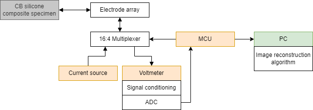
The hardware driving the ERT sensor consist of either one custom ERT PCB or a MUX PCB used with an ESP32 development board and source measurement unit (SMU). All of the files to create the hardware are given as raw KiCad files. All of the component libraries may not exist so will need to made manually or imported. SMU PCB pinout here
This board is for ERT data collection limited to sensor domains which have lower resisitances throughout the entirety of its intended use. The adjacent electrode resistance must not exceeed approx. 5 $k\Omega$.
This system consists of a SPI controlled 4:16 multiplexer (MUX) PCB used controlled with an ESP32 development board, PC and driven by a Keithley 2634b SMU and Keithley 2230G-30-1 DC power supply.
To run a test with the Cartesian force applicator see instructions in directory here
The PCB firmware is all written in C for the ESP32-WROOM SoC connected to a custom 'ERT PCB'. The firmware applies an electrode pattern to the electrodes and sends measurement data via the USB UART serial connection. The basic electrode drive process is:
This is a more modular approach so that we are not limited by the ERT PCB's current source and power supply values. This system has five main components: A Keithley 2634b SMU, a MUX PCB, an ESP32 WROOM32 development board, a Keithley 2230G-30-1 DC power supply, and a piezoresistive sensor domain. The whole system is controlled via the PCB connected to the ESP32 and SMU over UART. The basic electrode drive process is:
These steps are done using a PC to send commands for switching the MUC PCB and query messages sent to the SMU to get voltage and current values.
EIDORS was used as the library for image reconstruction using the data gathered from the PCB. A reference measurement is taken from the material on start-up of the reconstruction program. The reference measurement is compared to a current measurement for change in resisitvity (\Delta R) image reconstruction.
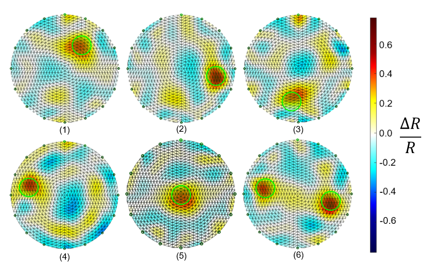
The rest of the physical system consists of:
| Qty | Value | Footprint | References |
|---|---|---|---|
| 23 | 100n | Capacitor_SMD:C_0603_1608Metric_Pad1.08x0.95mm_HandSolder | C3, C10, C11, C12, C13, C14, C15, C16, C17, C18, C19, C20, C25, C28, C30, C32 +7 |
| 10 | 10k | Resistor_SMD:R_0603_1608Metric_Pad0.98x0.95mm_HandSolder | R2, R6, R8, R15, R23, R24, R25, R26, R28, R32 |
| 9 | TestPoint | TestPoint:TestPoint_Pad_D1.5mm | 3V3_TP1, 5V_TP1, AGND1, GND1, ISRC1, V_IS1, VN1, VP1, VSS1 |
| 8 | 100R | Resistor_SMD:R_0603_1608Metric_Pad0.98x0.95mm_HandSolder | R1, R1, R2, R3, R4, R20, R21, R31 |
| 6 | 0R | Resistor_SMD:R_0603_1608Metric_Pad0.98x0.95mm_HandSolder | R7, R11, R12, R13, R14, R22 |
| 5 | 1u | Capacitor_SMD:C_0603_1608Metric_Pad1.08x0.95mm_HandSolder | C2, C5, C24, C33, C37 |
| 4 | DG406DYZ | DG406DYZ:SOIC28_7P60X18P10_INR-M | U2, U3, U4, U5 |
| 4 | MountingHole_Pad | MountingHole:MountingHole_3.2mm_M3_DIN965_Pad_TopBottom | H1, H2, H3, H4 |
| 3 | 10u | Capacitor_SMD:C_0603_1608Metric_Pad1.08x0.95mm_HandSolder | C26, C29, C31 |
| 3 | 150060VS75000 | LED_SMD:LED_0603_1608Metric_Pad1.05x0.95mm_HandSolder | D1, D6, D7 |
| 3 | 68R | Resistor_SMD:R_0603_1608Metric_Pad0.98x0.95mm_HandSolder | R3, R4, R5 |
| 3 | UAD8C05L01 | SOD882D:D_SOD-882 | D2, D3, D4 |
| 2 | 1k 1% | Resistor_SMD:R_0603_1608Metric_Pad0.98x0.95mm_HandSolder | R17, R19 |
| 2 | 1n | Capacitor_SMD:C_0603_1608Metric_Pad1.08x0.95mm_HandSolder | C21, C23 |
| 2 | 3k3 1% | Resistor_SMD:R_0603_1608Metric_Pad0.98x0.95mm_HandSolder | R16, R18 |
| 2 | 470n | Capacitor_SMD:C_0603_1608Metric_Pad1.08x0.95mm_HandSolder | C34, C36 |
| 2 | BC848 | Package_TO_SOT_SMD:SOT-23 | Q1, Q2 |
| 2 | Conn_01x02_Male | Connector_PinHeader_2.54mm:PinHeader_1x02_P2.54mm_Vertical | J2, J3 |
| 2 | Jumper_3_Open | Connector_PinHeader_1.27mm:PinHeader_1x03_P1.27mm_Vertical | JP2, JP3 |
| 2 | OPA2991IDR | OPA2991IDR:D0008A-MFG | U11, U12 |
| 2 | PTS636 SM50 SMTR LFS | Button_Switch_SMD:SW_SPST_B3U-1000P | SW2, SW3 |
| 2 | SN74HC595 | Package_SO:SOIC-16_3.9x9.9mm_P1.27mm | U6, U7 |
| 1 | 0R | Resistor_THT:R_Axial_DIN0204_L3.6mm_D1.6mm_P5.08mm_Vertical | R9 |
| 1 | 10K | Resistor_SMD:R_0603_1608Metric_Pad0.98x0.95mm_HandSolder | R27 |
| 1 | 10n | Capacitor_SMD:C_0603_1608Metric_Pad1.08x0.95mm_HandSolder | C22 |
| 1 | 200R | Resistor_SMD:R_0603_1608Metric_Pad0.98x0.95mm_HandSolder | R33 |
| 1 | 22K | Resistor_SMD:R_0603_1608Metric_Pad0.98x0.95mm_HandSolder | R29 |
| 1 | 47K | Resistor_SMD:R_0603_1608Metric_Pad0.98x0.95mm_HandSolder | R30 |
| 1 | 4u7 | Capacitor_SMD:C_0603_1608Metric_Pad1.08x0.95mm_HandSolder | C27 |
| 1 | 680R | Resistor_SMD:R_0603_1608Metric_Pad0.98x0.95mm_HandSolder | R10 |
| 1 | ADR5045BRTZ | Package_TO_SOT_SMD:SOT-23 | U16 |
| 1 | BAT760-7 | Diode_SMD:D_SOD-323 | D5 |
| 1 | CP2102N-A01-GQFN24 | Package_DFN_QFN:QFN-24-1EP_4x4mm_P0.5mm_EP2.6x2.6mm | U14 |
| 1 | C_Polarized | ECA1HM100B:CAP_PAN_5X11_PAN | C1 |
| 1 | Conn_01x12_Pin | Connector_PinHeader_2.54mm:PinHeader_1x12_P2.54mm_Vertical | J1 |
| 1 | Conn_01x16 | Connector_FFC-FPC:TE_1-84952-6_1x16-1MP_P1.0mm_Horizontal | J5 |
| 1 | Conn_01x16 | Connector_PinHeader_2.54mm:PinHeader_1x16_P2.54mm_Vertical | J6 |
| 1 | ESP32-WROOM-32 | RF_Module:ESP32-WROOM-32 | U1 |
| 1 | Jumper_2_Open | Connector_PinHeader_2.54mm:PinHeader_1x02_P2.54mm_Vertical | JP1 |
| 1 | LD1086DT33TR | Package_TO_SOT_SMD:TO-252-2 | U15 |
| 1 | LDK715M50R_SOT23-5 | Package_TO_SOT_SMD:SOT-23-5_HandSoldering | U17 |
| 1 | LTC1864 | Package_SO:SOIC-8_3.9x4.9mm_P1.27mm | U13 |
| 1 | MCP41HV51-103E/ST | Package_SO:TSSOP-14_4.4x5mm_P0.65mm | U8 |
| 1 | NTS0104BQ | vt-footprints:DHVQFN14-2.5x3 | U10 |
| 1 | PSSI2021SAY | Package_TO_SOT_SMD:SOT-353_SC-70-5 | U9 |
| 1 | PTS636 | Button_Switch_SMD:SW_SPST_B3U-1000P | SW1 |
| 1 | TP_s | TestPoint:TestPoint_Pad_D2.0mm | BOOT1 |
| 1 | USB_C_HEADER | USB-C-GTC:GCT_USB4105-GF-A | J4 |
richgumy/black_sensor
A sensor developed using solely a carbon black silicone elastomer composite and the driving electronics.


wemaxon/esp32-audio-streamer
Hardware design for a WiFi/Bluetooth audio streamer using the esp32 microcontroller and the PCM5102A DAC, intended to be used with squeezelite firmware.


plantbot/core_pcb
A WiFi powered environmental sensor board for your house plants & hydroponic systems


lukasprojects/esp32-dalitester
Small ESP32 DALI tester for commissioning and maintaining light installations via the DALI bus


Roshan-khatri78/Electronics-Projects-KiCad-
A collection of my KiCad projects and PCB designs. These projects reflect my learning journey in electronics and PCB design.
It measures 79.5 × 94.4 mm and has 4 copper layers, 1.6 mm thick.
127 parts, built around the CP2102N-A01-GQFN24, ESP32-WROOM-32, PSSI2021SAY and DG406DYZ. The full list of its parts is on this page, with links to each part's symbol and footprint where PCBKit's library has them.
From the richgumy/black_sensor repository on GitHub, at the commit this page was made from: the board is pcb-hardware/HV_ERT_sensor/HV_ERT_sensor.kicad_pcb and its schematic pcb-hardware/HV_ERT_sensor/HV_ERT_sensor.kicad_sch. PCBKit opens the board in the browser, with nothing to install.
Its repository states no licence, so its author keeps all rights: ask richgumy before reusing the design.