Skip to the content
2 layers110.3 × 110.3 mmH Bridge PCB, the printed circuit board in 3D

The project consists of two main components: 1. HBridgePCBDesign — KiCad PCB layout and schematic. 2. HBridgePCBCode — Firmware for the ESP32 controller.

Size
110.3 × 110.3 mm
Copper layers
2
Thickness
1.6 mm
Parts
124
Nets
95
Pads
392
Tracks, vias
962, 160
Pours
4
Routed
Yes
KiCad
KiCad 9.0 (file 20241229)
Created
31 Jan 2025
Updated
15 Dec 2025

Overview

H Bridge PCB is an open-source printed circuit board by reinto1234, from the reinto1234/H_Bridge_PCB repository on GitHub. It is a 2-layer board of 110.3 × 110.3 mm with 124 parts on 95 nets, routed with 962 tracks and 160 vias.

It is built around the CH340C, ESP32-WROOM-32 and NXJ1S0303MC-R13, with the IR2110S-MNS, AMC1306M25DWVR and L7812ABD2T-TR among its other parts. Its parts include 36 capacitors, 30 resistors, 16 diodes, 11 connectors and 10 ICs. It belongs with the interfaces and adapters boards and the ESP32 boards of this library.

Main components

12

README

README.md

H-Bridge PCB Project

Project Description

This project involves the design and implementation of an educational single-phase H-Bridge inverter controlled by an Espressif ESP32.
The system demonstrates bipolar sinusoidal PWM (SPWM) operation with closed-loop VRMS amplitude control and a browser-based interface for monitoring and control.
The H-Bridge can drive loads with the following ratings:

  • Input Voltage: 24 V
  • Input Current: up to 10 A
  • Power: ≈ 240 W

Features

  • Fixed switching frequency: 35 kHz
  • Fixed output frequency: 50 Hz
  • Bipolar SPWM modulation (only)
  • Closed-loop VRMS control using PI regulation
  • Web-based UI (HTTP + WebSocket) for control and telemetry
  • Input/Output power measurement
  • Overcurrent protection using INA228 (auto driver shutdown + UI fault latch)

The project consists of two main components:

  1. H_Bridge_PCB_Design — KiCad PCB layout and schematic.
  2. H_Bridge_PCB_Code — Firmware for the ESP32 controller.

Directory Structure

Directory Structure

text
H_Bridge_PCB_Project/
├── H_Bridge_PCB_Design/        # KiCad design files
├── H_Bridge_PCB_Code/          # ESP32 firmware
│   ├── include/                # Header files
│   │   ├── Controller.h
│   │   ├── I2C.h
│   │   ├── Input_meas.h
│   │   ├── mutexdefinitions.h
│   │   ├── Output_meas.h
│   │   ├── PWM.h
│   │   ├── spi_sampler.h
│   │   ├── Tasks.h
│   │   └── webserver.h
│   │
│   ├── src/                    # Source files
│   │   ├── Controller.cpp
│   │   ├── I2C.cpp
│   │   ├── Input_meas.cpp
│   │   ├── Output_meas.cpp
│   │   ├── PWM.cpp
│   │   ├── spi_sampler.cpp
│   │   ├── Tasks.cpp
│   │   ├── webserver.cpp
│   │   └── main.cpp

Requirements

Hardware:

  • PCB based on KiCad design
  • 24 V DC power supply (≥ 10 A)
  • Resistive or inductive load (max ≈ 240 W)
  • Gate drivers with integrated dead-time
  • INA228 current/voltage monitor for input sensing

Software:


Webserver

The ESP32 provides a built-in Wi-Fi access point and hosts a web-based interface for control and measurement visualization.

Connect to WLAN Access Point

  • SSID: H_Bridge_Control
  • Password: 12345678

Open the web interface:

👉 http://192.168.4.1/

Functions:

  • Start/Stop the inverter
  • Set VRMS target
  • Display live telemetry (Vin, Iin, VRMS, IRMS, PF, P, Q, f)
  • View and acknowledge overcurrent faults

Code

The firmware is implemented in C++ (Arduino / FreeRTOS).
The web interface is built with HTML, JavaScript, and CSS.


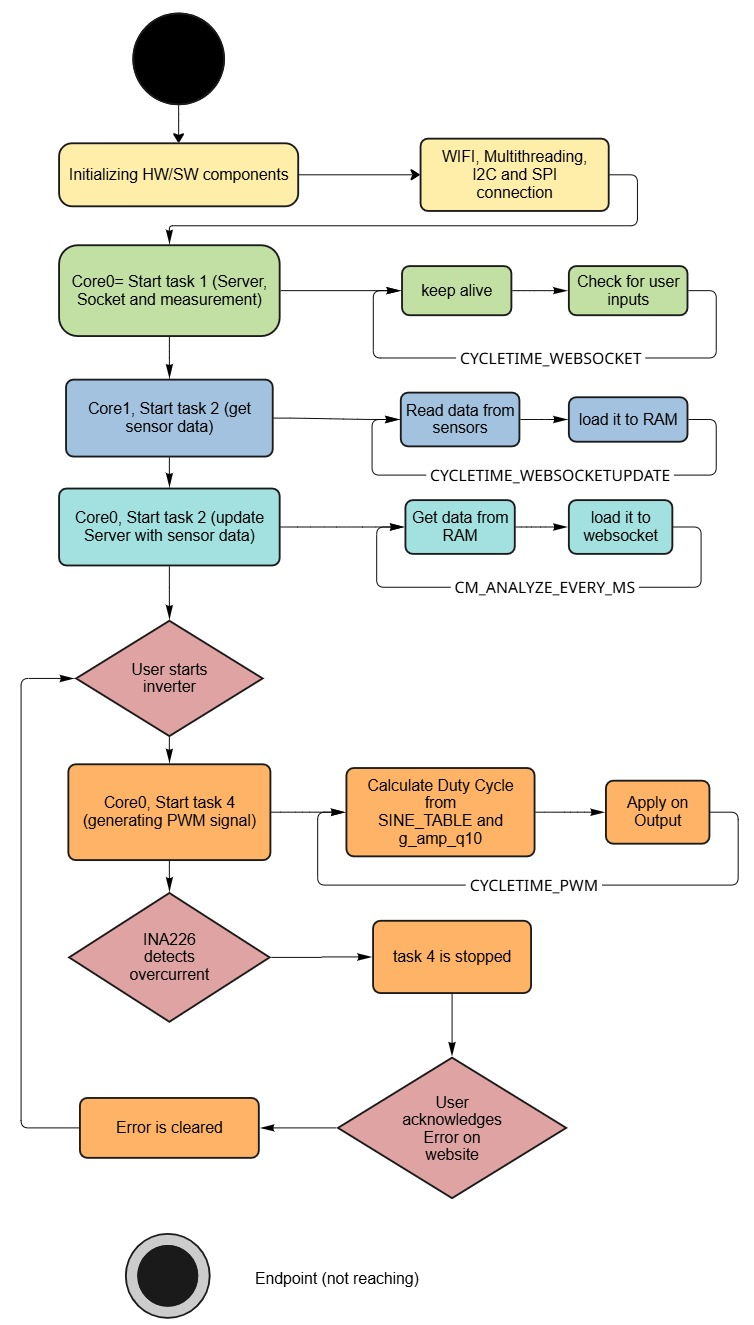
Flowchart

Flowchart of the program


Code Documentation

Brief overview of the most relevant components.

Inverter Implementation (PWM.cpp)

Implements the real-time control of the full-bridge inverter:

  • startInverter() — Initializes and enables PWM output.
  • stopInverter() — Stops PWM and resets inverter state.
  • generateSPWM() — Produces bipolar SPWM using a sine table.
  • begin() — Configures LEDC channels, frequency, and timers.
  • getMeasurements() — Retrieves latest measurement snapshot.
  • computePI() — Executes PI algorithm to maintain VRMS target.
  • loop() — Runs the inverter control logic at fixed timing intervals.

Controller Implementation (Controller.cpp)

Implements the PI controller used to regulate the inverter’s RMS output voltage:

  • PIController() — Initializes PI gains, integrator state, limits, and VRMS target.
  • ControlRMS() — Computes RMS error and updates the global Q10 amplitude factor atomically.
  • compute() — Executes PI algorithm with anti-windup and output clamping to min/max limits.
  • g_amp_q10 — Global Q10-formatted amplitude value used by the SPWM stage.

I²C Bus Setup (I2C.cpp)

Implements the I²C interface for the INA228 current/voltage sensor:

  • I2CINA — Dedicated I²C bus instance (port 0) used by the input measurement subsystem.

Input Measurement (Input_meas.cpp)

Implements DC input voltage, current, and power measurement using INA228:

  • init() — Initializes I²C bus, scans for devices, configures INA228, and sets averaging/timing.
  • init1() — Lightweight I²C initialization helper without full sensor setup.
  • configure_overcurrent_alert_only() — Configures INA228 alert registers for shunt overcurrent shutdown.
  • getVoltage() — Reads and returns the DC input voltage in volts.
  • getCurrent() — Reads and returns the shunt current in amperes.
  • getPower() — Reads and returns the input power in watts with simple error rejection.
  • measurementall() — Updates the shared input measurement buffer (voltage, current, power) in a mutex-protected way and returns it.
  • scanI2C() — Scans the I²C bus, prints found devices, and restarts the bus if no device is detected.

Main Application (main.cpp)

Implements system bring-up and FreeRTOS task orchestration:

  • setup() — Initializes serial logging, mutexes, input measurement, Wi-Fi AP, webserver, SPI measurement engines, safety pins, and the overcurrent interrupt; then creates all application tasks.
  • loop() — Empty main loop; periodically yields since all logic is implemented in FreeRTOS tasks.
  • Task handles — Stores references to sampler, analyzer, WebSocket, controller, printer, and emergency stop tasks for debugging/management.

Mutex Definitions (mutexdefinitions.cpp)

Implements globally shared FreeRTOS mutexes for synchronization:

  • inverterMutex — Protects access to the inverter state and control functions.
  • measurementinMutex — Protects shared input measurement buffer.
  • measurementoutMutex — Protects shared output measurement structures.
  • measurementSpiMutex — Protects SPI-related measurement buffers and state.

Output Measurement (Output_meas.cpp)

Implements decimation, CIC filtering, RMS, and frequency analysis for AMC1306 bitstreams:

  • buildByteCicLut() — Precomputes CIC integrator/differentiator contributions for all 8-bit patterns.
  • OutputMeasurements() — Configures OSR, full-scale voltage, buffer sizes, and initial bit rate.
  • init() — Allocates decimation ring buffers, analysis windows, and period buffers (with PSRAM support) and creates a snapshot mutex.
  • copyRecentWindowWithStats() — Copies the newest segment from the decimation ring and computes mean, min, and max.
  • findLastTwoRisingZcHyst() — Detects the last two rising zero-crossings with hysteresis to define one AC period.
  • computeRmsOnePeriodExact() — Computes exact RMS over one period using piecewise linear interpolation.
  • processRxBytesAndUpdateBitrate() — Processes raw SPI bytes, runs CIC pipeline, generates decimated voltage samples, and updates effective bit rate.
  • analyzeStep() — Centers the signal, finds period boundaries, computes frequency, extracts a centered period, and calculates RMS.
  • getSnapshot() — Returns the latest snapshot (RMS, frequency, period length) in a thread-safe way.
  • copyLastPeriod() — Copies the last detected waveform period into a caller-provided buffer.
  • copySinceSeq32() — Provides incremental decimated samples since a given sequence index, for streaming or plotting.

Emergency Stop (safety.cpp)

Implements minimal emergency-stop signaling for overcurrent events:

  • g_emergency_stop — Global volatile flag indicating an active emergency stop condition.
  • onAlertISR() — ISR that sets the emergency stop flag when the INA228 alert pin fires.

SPI Sampler (spi_sampler.cpp)

Implements DMA-driven SPI acquisition for dual AMC1306 isolated ADC channels:

  • g_ch1_om / g_ch2_om — OutputMeasurements instances for both channels with hardware-specific scaling.
  • g_sampler1 / g_sampler2 — Sampler context structures for SPI hosts, pins, DMA channels, and transactions.
  • g_pack1 / g_pack2 — Pairs of sampler context and OutputMeasurements used by sampler tasks.
  • spiSamplerInitMeasurements() — Initializes both OutputMeasurements engines and validates buffer allocation.
  • spiInitAndStart() — Allocates DMA buffers, configures SPI bus and device, prepares transactions, and seeds the transaction queue.

Task Scheduler (Tasks.cpp)

Implements all FreeRTOS tasks for sampling, analysis, UI updates, control, and safety:

  • spiSamplerTask() — Retrieves completed SPI DMA transactions, feeds data into OutputMeasurements, requeues transactions, and maintains sampling timing.
  • analyzerTask() — Periodically calls analyzeStep() on a given OutputMeasurements instance to update RMS and frequency.
  • printerTask() — Periodically prints analyzer timing, latest period samples, RMS, and frequency for both channels over serial.
  • webSocketTask() — Processes WebSocket events in a loop to keep client connections responsive.
  • webSocketUpdate() — Periodically collects input and output measurements and sends them as JSON via WebSocket to the UI.
  • ControllerTask() — Runs the VRMS control loop by feeding the measured RMS value into the PI controller of the inverter.
  • EmergencyStopTask() — Monitors the global emergency-stop flag, stops the inverter, signals the E-STOP output, and notifies the web UI when overcurrent is detected.

Webserver (webserver.cpp)

Implements Wi-Fi access point, HTTP endpoints, and WebSocket telemetry/UI control:

  • resetDefaults() — Resets VRMS target and running state to their default values.
  • initWiFi() — Starts the Wi-Fi SoftAP for the H-Bridge control interface.
  • initServer() — Mounts LittleFS, serves static /index.html, /style.css, /script.js, and defines /start, /stop, and /ack-trip endpoints.
  • updateMeasurements() — Packs input/output data and frequency into JSON and broadcasts it over WebSocket.
  • broadcastStatus() — Sends current inverter running state to all connected clients via WebSocket.
  • onWebSocketEvent() — Handles client connect/disconnect events and sends initial status on connect.
  • broadcastTrip() — Notifies all clients of a trip condition and updates running state.
  • _VRMS / _isRunning — Static internal state for desired RMS value and inverter run/stop status.

HTTP Endpoints:

  • / – Main HTML page
  • /start – Start inverter
  • /stop – Stop inverter
  • /update – Update VRMS target
  • /bipolar.png – Waveform reference

Overcurrent Protection

Overcurrent protection is implemented through the INA228 fault pin:

  1. When a current threshold is exceeded, drivers are disabled immediately.
  2. A fault message is sent to the web interface.
  3. After user acknowledgment, the inverter can be restarted safely.

Safety

  • Use current-limited power supplies during development.
  • Verify MOSFET temperature and load ratings.
  • For educational/laboratory use only.

License

Released for educational and research purposes.
Use responsibly.

Parts

124
QtyValueFootprintReferences
10100 nFResistor_SMD:R_0805_2012Metric_Pad1.20x1.40mm_HandSolderC9, C10, C13, C18, C19, C22, C24, C30, C33, C35
10TSW-102-15-T-SSamacSys_Parts:TSW-102-XX-YY-SJ1, J2, J3, J4, J5, J7, J9, J12, J14, J15
810kResistor_SMD:R_0805_2012Metric_Pad1.20x1.40mm_HandSolderR4, R5, R6, R7, R30, R31, R40, R41
61µFResistor_SMD:R_0805_2012Metric_Pad1.20x1.40mm_HandSolderC11, C17, C21, C25, C26, C27
6S210SamacSys_Parts:DIOM5336X265ND6, D7, D8, D9, D10, D11
51 µFResistor_SMD:R_0805_2012Metric_Pad1.20x1.40mm_HandSolderC12, C31, C32, C34, C36
40Resistor_SMD:R_0805_2012Metric_Pad1.20x1.40mm_HandSolderR19, R20, R23, R24
410Resistor_SMD:R_0805_2012Metric_Pad1.20x1.40mm_HandSolderR2, R3, R8, R9
4575-4SamacSys_Parts:5754TP1, TP2, TP3, TP4
4FSV2060LSamacSys:FSV2060LD1, D2, D3, D5
4IPD90N10S4L06ATMA1SamacSys:IPD90N10S4L06ATMA1Q5, Q6, Q9, Q10
4IRLB4030PBFSamacSys:TO254P483X1016X1994-3PQ1, Q2, Q3, Q4
3100uFSamacSys_Parts:EEE1AA101SPC7, C8, C23
21 uFResistor_SMD:R_0805_2012Metric_Pad1.20x1.40mm_HandSolderC28, C29
2100Resistor_SMD:R_0805_2012Metric_Pad1.20x1.40mm_HandSolderR11, R27
212kResistor_SMD:R_0805_2012Metric_Pad1.20x1.40mm_HandSolderR13, R18
21kResistor_SMD:R_0805_2012Metric_Pad1.20x1.40mm_HandSolderR17, R28
22.2Resistor_SMD:R_0805_2012Metric_Pad1.20x1.40mm_HandSolderR1, R10
22.2 uFResistor_SMD:R_0805_2012Metric_Pad1.20x1.40mm_HandSolderC1, C6
222 nFResistor_SMD:R_0805_2012Metric_Pad1.20x1.40mm_HandSolderC3, C5
2220 nFResistor_SMD:R_0805_2012Metric_Pad1.20x1.40mm_HandSolderC2, C4
2220nFResistor_SMD:R_0805_2012Metric_Pad1.20x1.40mm_HandSolderC14, C15
2AMC1306M25DWVRSamacSys:SOIC127P1150X280-8NIC1, IC3
2BC817Package_TO_SOT_SMD:SOT-23_HandsolderingQ7, Q8
2GMR100HTBFER015Resistor_SMD:R_2512_6332Metric_Pad1.40x3.35mm_HandSolderR15, R42
2IR2110SPackage_SO:SOIC-16W_7.5x10.3mm_P1.27mmU2, U3
2TLMG1100-GS15-1Resistor_SMD:R_0805_2012Metric_Pad1.20x1.40mm_HandSolderLED1, LED4
11Resistor_SMD:R_0805_2012Metric_Pad1.20x1.40mm_HandSolderR12
1120kResistor_SMD:R_0805_2012Metric_Pad1.20x1.40mm_HandSolderR16
11734510-1SamacSys_Parts:17345101J13
1330Resistor_SMD:R_0805_2012Metric_Pad1.20x1.40mm_HandSolderR29
14.7 µFResistor_SMD:R_0805_2012Metric_Pad1.20x1.40mm_HandSolderC20
15kResistor_SMD:R_0805_2012Metric_Pad1.20x1.40mm_HandSolderR14
1B32776E4406J000SamacSys_Parts:B32776E4406J000C16
1B3U-1000PSamacSys:B3U-1000PS1
1CH340CPackage_SO:SOIC-16_3.9x9.9mm_P1.27mmU7
1ESP32-WROOM-32RF_Module:ESP32-WROOM-32U1
1HPZR-C26XSamacSys_Parts:HPZRC26XD12
1INA228Package_SO:VSSOP-10_3x3mm_P0.5mmU4
1L7812ABD2T-TRSamacSys:L7812ABD2TTRIC2
1LD1086DT50TRPackage_TO_SOT_SMD:TO-252-2U6
1LT1963AxST-3.3Package_TO_SOT_SMD:SOT-223-3_TabPin2U5
1NXJ1S0303MC-R13SamacSys:NXJ1S0303MCR13PS1
1PHBC24N-2R0A0219VSamacSys_Parts:PHBC24N2R0A0219VFL1
1SP0503BAHTPackage_TO_SOT_SMD:SOT-143D4
1TLMG1100-GS15-2Resistor_SMD:R_0805_2012Metric_Pad1.20x1.40mm_HandSolderLED2
1TLMG1100-GS15-3Resistor_SMD:R_0805_2012Metric_Pad1.20x1.40mm_HandSolderLED3

The 120 most common of 124 parts.

Similar boards

  • 4 layers138.2 × 200.4 mmHV servo drive v1, the printed circuit board in 3D

    HV servo drive v1

    ExcessiveMotion/drive-hardware

    383 parts175CERN-OHL-W-2.0
  • 4 layers449.2 × 272.9 mmWpc power driver cost, the printed circuit board in 3D

    Wpc power driver cost

    lolz0r/Williams-WPC-Power-Driver-Board-A-12697-3

    Untested, unverifed, AI created design.

    453 parts2
  • 2 layers80 × 52.8 mmLemon F334-K, the printed circuit board in 3D

    Lemon F334-K

    NickNifontov/CipollinoRTOS

    Sin wave invertor (HRPWM, 35kHz). Replacement for TL/EG PWM .

    176 parts3
  • 2 layers310 × 100 mmAOML AB 3.0 reorganized v2, the printed circuit board in 3D

    AOML AB 3.0 reorganized v2

    cxs1529/XBT_Autolauncher_PCB

    KiCAD repository for the XBT Autolauncher board

    247 parts
  • 4 layers100 × 100 mmDeneme2, the printed circuit board in 3D

    Deneme2

    Gokasimov/STM32-FOC-Control

    A completely from-scratch, bare-metal implementation of Field-Oriented Control (FOC) tailored for ultra-low inductance (3 µH) drone motors (e.g., A2212).

    118 parts2MIT
  • 4 layers90 × 53.5 mmBuck boost solar, the printed circuit board in 3D

    Buck boost solar

    JonasCz/lt8491-charger-boards

    Boosting high-voltage MPPT solar charger based on LT8491

    129 parts2
  • 2 layers85.3 × 50.3 mmBeef bridge, the printed circuit board in 3D

    Beef bridge

    anuejn/beef_bridge

    An IGBT-half-bridge-board

    36 parts1

Questions

How big is the H Bridge PCB PCB?

It measures 110.3 × 110.3 mm and has 2 copper layers, 1.6 mm thick.

What parts does the H Bridge PCB use?

124 parts, built around the CH340C, ESP32-WROOM-32, NXJ1S0303MC-R13 and IR2110S-MNS. The full list of its parts is on this page, with links to each part's symbol and footprint where PCBKit's library has them.

Where can I download the H Bridge PCB KiCad files?

From the reinto1234/H_Bridge_PCB repository on GitHub, at the commit this page was made from: the board is H_bridge_PCB_Design/H_bridge_PCB.kicad_pcb and its schematic H_bridge_PCB_Design/H_bridge_PCB.kicad_sch. PCBKit opens the board in the browser, with nothing to install.

Can I use the H Bridge PCB design in my own project?

Its repository states no licence, so its author keeps all rights: ask reinto1234 before reusing the design.