2 layers28.3 × 39.8 mm
LevelShifter
gusmanb/logicanalyzer
24 channel, 100Msps logic analyzer hardware and software
21 parts5.1kGPL-3.0

 reimunyancat/hackpad
A custom 9-key (3x3 matrix) macropad with a rotary encoder and a 1.3" OLED, built for the Hack Club Stardance Hackpad YSWS.
Hackpad is an open-source printed circuit board by reimunyancat, from the reimunyancat/hackpad repository on GitHub. It is a 2-layer board of 57 × 78 mm with 21 parts on 24 nets, routed with 130 tracks and 0 vias.
Its parts include 10 switches, 9 diodes, 1 IC and 1 connector. It belongs with the RP2040 boards of this library.
A custom 9-key (3x3 matrix) macropad with a rotary encoder and a 1.3" OLED, built for the Hack Club Stardance Hackpad YSWS.
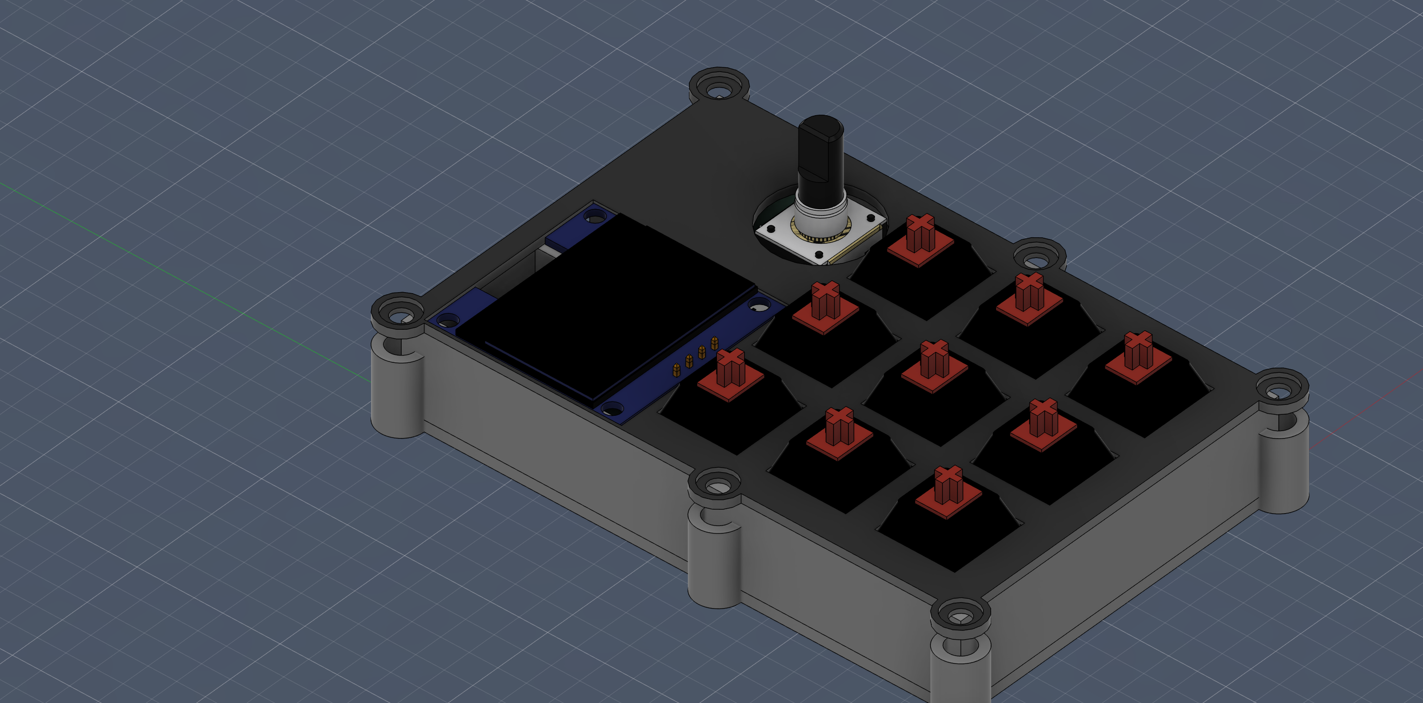
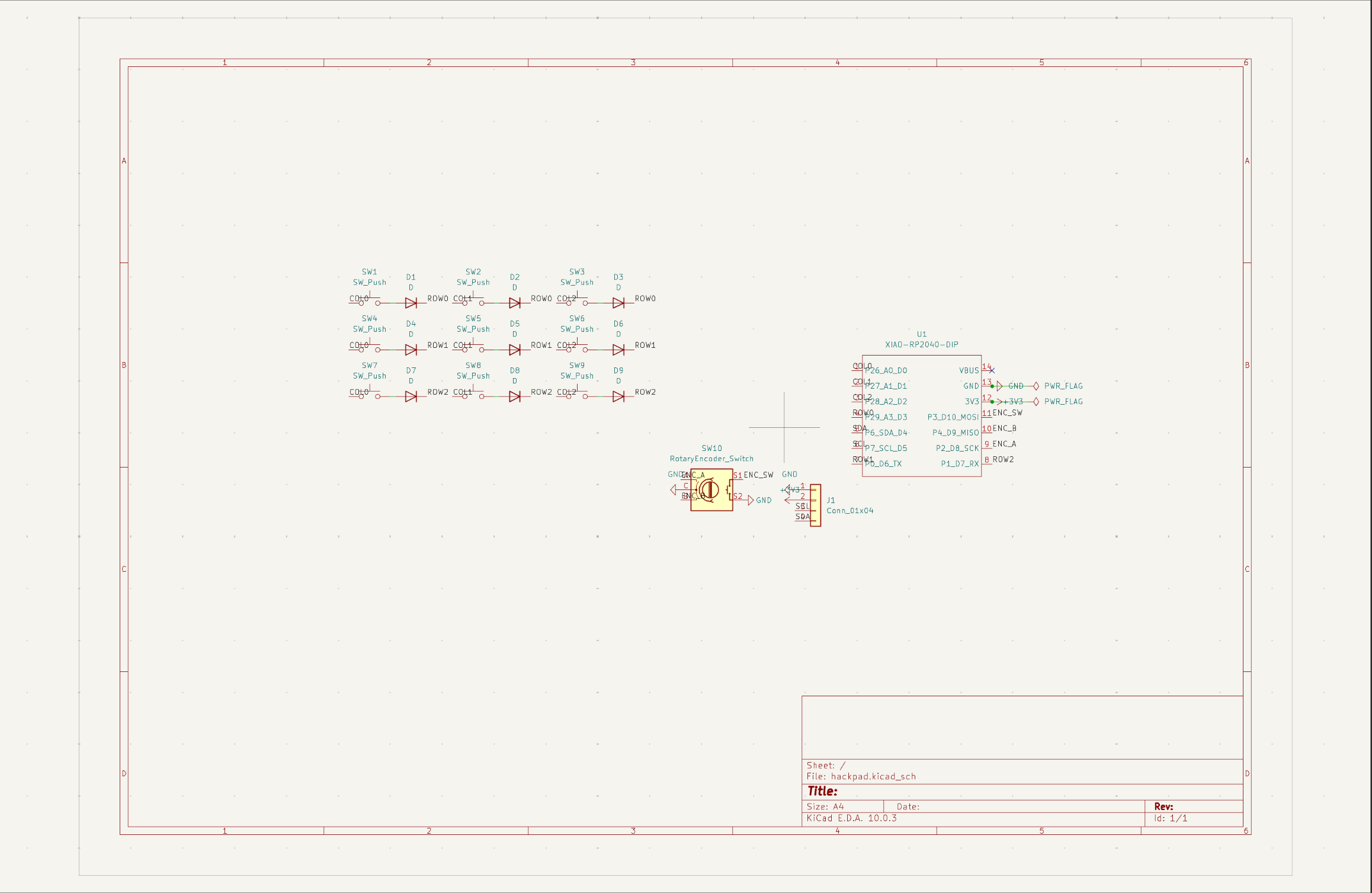
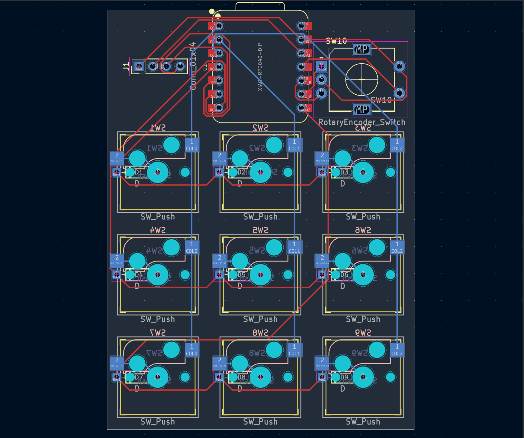
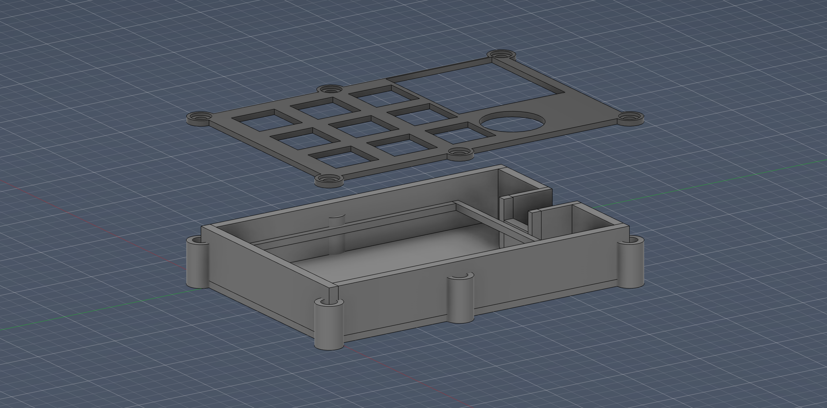
| Component | Qty | Notes |
|---|---|---|
| Seeed XIAO RP2040 | 1 | MCU (kit) |
| 1N4148 diode | 9 | matrix anti-ghosting (kit) |
| MX-style switch | 9 | (kit) |
| Kailh MX hotswap socket | 9 | self-sourced |
| EC11 rotary encoder | 1 | 20mm D-shaft (kit) |
| 1.3" 128x64 SH1106 OLED | 1 | I2C, self-sourced |
| 2.54mm 4-pin female header | 1 | OLED mount, self-sourced |
| DSA keycap | 9 | (kit) |
| M3x16 screw | 6 | (kit) |
| M3x5x4 heatset insert | 6 | (kit) |
| Custom PCB | 1 | JLCPCB, 2-layer, ~57x79mm |
| 3D printed case | 1 | top plate + bottom shell |
.
├── README.md
├── CAD/
│   └── assembled-model.STEP
├── PCB/
│   ├── hackpad.kicad_pro
│   ├── hackpad.kicad_sch
│   └── hackpad.kicad_pcb
├── Firmware/
│   └── main.py
└── production/
    ├── gerbers.zip
    ├── Top.STEP
    ├── Bottom.STEP
└── main.pyKMK (CircuitPython). Flash CircuitPython to the XIAO, copy the kmk library folder onto the CIRCUITPY drive, then drop Firmware/main.py on it.
Pin mapping (taken from the schematic):
Note: I need a soldering iron — please include the $18 soldering iron grant.
| Qty | Value | Footprint | References |
|---|---|---|---|
| 9 | D | Diode_THT:D_DO-35_SOD27_P7.62mm_Horizontal | D1, D2, D3, D4, D5, D6, D7, D8, D9 |
| 9 | SW_Push | keyswitches:Kailh_socket_MX | SW1, SW2, SW3, SW4, SW5, SW6, SW7, SW8, SW9 |
| 1 | Conn_01x04 | Connector_PinHeader_2.54mm:PinHeader_1x04_P2.54mm_Vertical | J1 |
| 1 | RotaryEncoder_Switch | Rotary_Encoder:RotaryEncoder_Alps_EC11E-Switch_Vertical_H20mm | SW10 |
| 1 | XIAO-RP2040-DIP | Seeed_Studio_XIAO_Series:XIAO-RP2040-DIP | U1 |
It measures 57 × 78 mm and has 2 copper layers, 1.6 mm thick.
21 parts. The full list of its parts is on this page, with links to each part's symbol and footprint where PCBKit's library has them.
From the reimunyancat/hackpad repository on GitHub, at the commit this page was made from: the board is PCB/hackpad.kicad_pcb and its schematic PCB/hackpad.kicad_sch. PCBKit opens the board in the browser, with nothing to install.
Its repository states no licence, so its author keeps all rights: ask reimunyancat before reusing the design.
gusmanb/logicanalyzer
24 channel, 100Msps logic analyzer hardware and software

mntmn/amiga2000-gfxcard
MNT VA2000, an Open Source Amiga 2/3/4000 Graphics Card (Zorro II/III), written in Verilog


hackclub/OnBoard
💡 Join 1,000 teenagers and make your first PCB with a $100 grant!

drandyhaas/KiCadRoutingTools
A set of Python/Rust tools to aid routing in KiCad

Arrow-air/project-quiver
Project Quiver documentation, designs, and project artifacts.

