2 layers50.8 × 76.2 mm
Breadboard-1
bicknell/DCC-Mobile-Decoder
DCC Mobile Decoder Reference Implementation Hardware & Software
76 parts14

 RedlabsDE/Digital-DC-Load
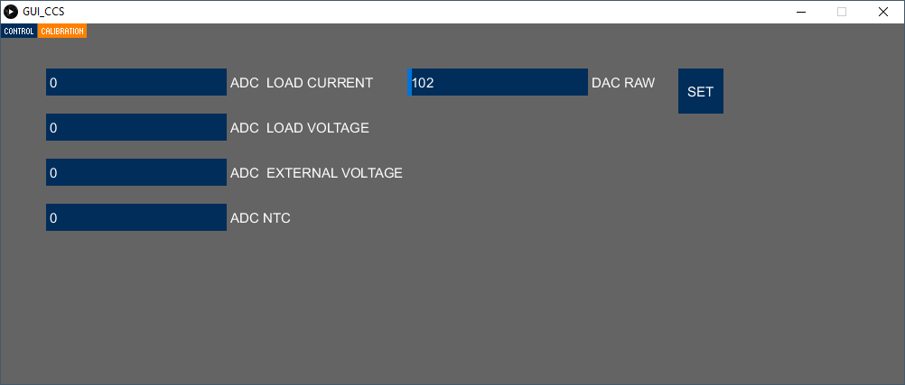
In the "Calibration" page, the raw ADC values are displayed. The user can set the raw DAC value.
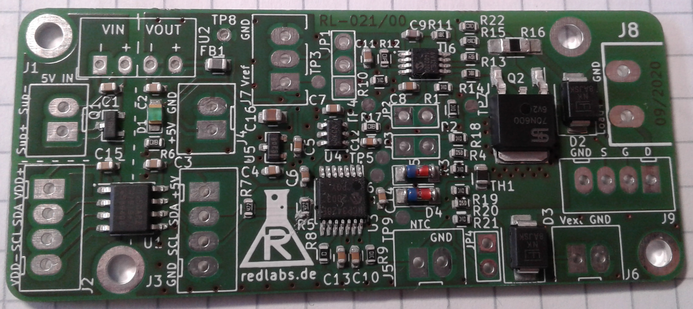
021-00 Digital DC Load is an open-source printed circuit board by RedlabsDE, from the RedlabsDE/Digital-DC-Load repository on GitHub. It is a 2-layer board of 70 × 30 mm with 78 parts on 35 nets, routed with 427 tracks and 125 vias.
It is built around the AM1S-0505SZ, MCP3428-E/SL and ADUM1250AR, with the MCP6V12-E/MS, SMBJ60A and PMV250EPEAR among its other parts. Its parts include 22 resistors, 16 capacitors, 9 connectors, 6 ICs and 5 diodes.


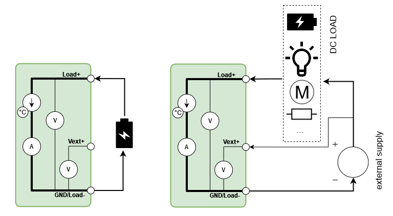
key features:
example application:
DigitalLoadExample, inlcuding a C++ class RL021_DigitalLoad for easy control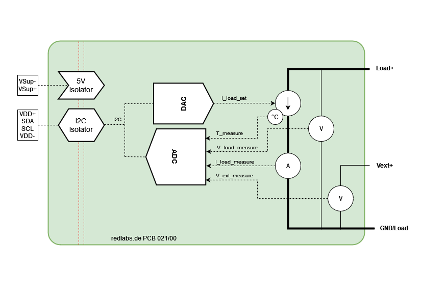
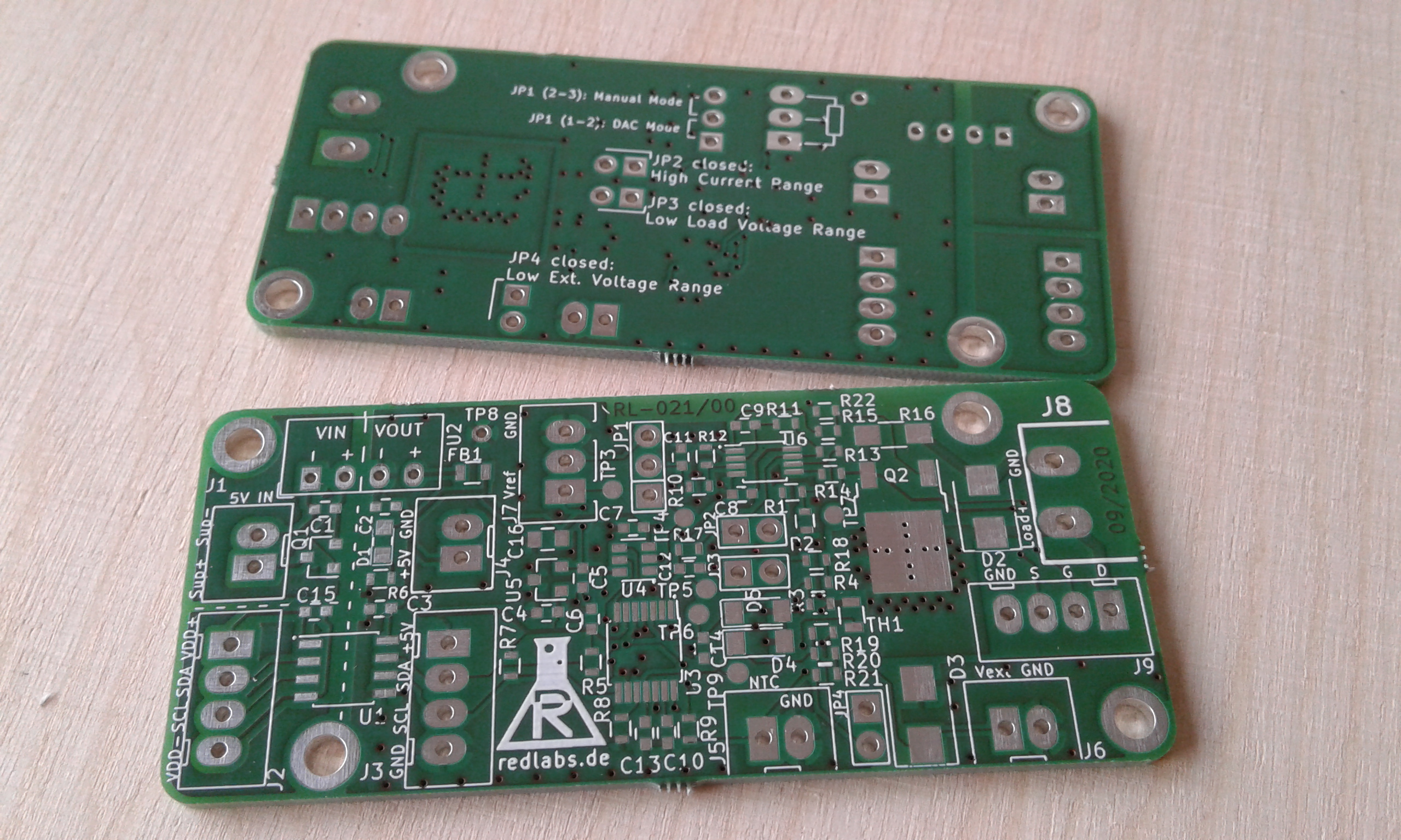
Order PCB: https://aisler.net/p/YHESFYKF
Via multiple jumpers the used operating ranges can be configured.
| Parameter | Jumper | open | closed |
|---|---|---|---|
| Current Control | JP1 | External analog signal | Digital via onboard DAC |
| I_load range | JP2 | low 0-1A | high 0-10A |
| V_load range | JP3 | high 0-24V | 0-4V |
| V_extern range | JP4 | high 0-24V | 0-4V |
| ADC I2C Addr (A2,A1,A0) | R8 | 0,0,1 | 0,0,0 |
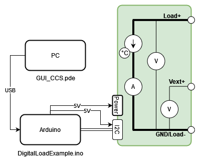
| Signal | Arduino Pin |
|---|---|
| I2C_VDD (J2, pin1) | 5V |
| I2C_SDA (J2, pin2) | A4 |
| I2C_SCL (J2, pin3) | A5 |
| I2C_GND (J2, pin4) | GND |
| SUPPLY_+5V (J1, pin1) | 5V |
| SUPPLY_GND (J1, pin2) | GND |
	/// Write board jumper settings (like set on PCB)
	myLoad.SetJumperSetting(JP2_CURRENT,Jumper_Closed);
	myLoad.SetJumperSetting(JP3_VLOAD,Jumper_Open);
myLoad.SetJumperSetting(JP4_VEXT,Jumper_Open); An example PC-based user interface (written in "Processing"), for the use with the firmware/DigitalLoadExample project.
  String portName = Serial.list()[0];
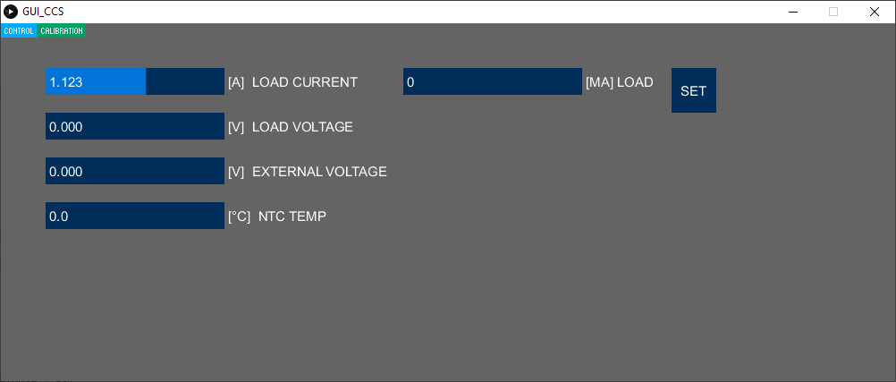
myPort = new Serial(this, portName, 115200);In the "Control" page, all measured values are displayed in SI-units. The user can set the desired load current in mA.
In the "Calibration" page, the raw ADC values are displayed. The user can set the raw DAC value.
... find other projects: https://redlabs.de/
| Qty | Value | Footprint | References |
|---|---|---|---|
| 10 | 100n | Capacitors_SMD:C_0603 | C1, C2, C3, C4, C5, C6, C7, C8, C11, C15 |
| 5 | 10k | Resistors_SMD:R_0603 | R2, R3, R9, R10, R19 |
| 4 | 1n | Capacitors_SMD:C_0603 | C10, C12, C13, C14 |
| 4 | Conn_01x02 | redLabs-new:JST_XH2P_oval_pads | J1, J4, J5, J6 |
| 4 | MountingHole | Mounting_Holes:MountingHole_2.7mm_M2.5_DIN965_Pad | H1, H2, H3, H4 |
| 3 | 11k | Resistors_SMD:R_0603 | R1, R18, R21 |
| 3 | Conn_01x04 | redLabs-new:JST_XH4P_oval_pads | J2, J3, J9 |
| 3 | Jumper | redLabs-new:PIN_ARRAY_2X1_big_pads | JP2, JP3, JP4 |
| 2 | 110k | Resistors_SMD:R_0603 | R4, R20 |
| 2 | 15k | Resistors_SMD:R_0603 | R11, R14 |
| 2 | 1k | Resistors_SMD:R_0603 | R6, R17 |
| 2 | 4k7 | Resistors_SMD:R_0603 | R5, R7 |
| 2 | SMBJ60A | redLabs-new:D_SMB_bidirectional | D2, D3 |
| 2 | ZF5.1 | redLabs-new:D_MiniMELF | D4, D5 |
| 1 | 0R1 | Resistors_SMD:R_1206_HandSoldering | R16 |
| 1 | 100 | Resistors_SMD:R_0603 | R15 |
| 1 | 100k | Resistors_SMD:R_0603 | R22 |
| 1 | 10M | Resistors_SMD:R_0603 | R12 |
| 1 | 10u | Capacitors_SMD:C_0805 | C16 |
| 1 | 190k | Resistors_SMD:R_0603 | R13 |
| 1 | 22p | Capacitors_SMD:C_0603 | C9 |
| 1 | ADuM1250 | Housings_SOIC:SOIC-8_3.9x4.9mm_Pitch1.27mm | U1 |
| 1 | AM1S-0505 | redLabs-new:DCDC-Isolated-SIP4 | U2 |
| 1 | BLM21PG 300 | Resistors_SMD:R_0805 | FB1 |
| 1 | Conn_01x02 | redLabs-new:AKL_2_RM508_RND205-00199 | J8 |
| 1 | Conn_01x03 | redLabs-new:JST_XH3P_oval_pads | J7 |
| 1 | GND | Measurement_Points:Measurement_Point_Round-TH_Small | TP8 |
| 1 | JUMPER | Resistors_SMD:R_0603 | R8 |
| 1 | Jumper_3_Bridged12 | redLabs-new:PIN_ARRAY_3X1_big_pads | JP1 |
| 1 | LED | redLabs-new:LED_0805 | D1 |
| 1 | LOGO | redLabs-new:RL_LOGO3_schrift | G*** |
| 1 | MCP3428 | Housings_SSOP:TSSOP-14_4.4x5mm_Pitch0.65mm | U3 |
| 1 | MCP4726 | TO_SOT_Packages_SMD:SOT-23-6 | U4 |
| 1 | MCP6V12 | Housings_SSOP:MSOP-8_3x3mm_Pitch0.65mm | U6 |
| 1 | PMV250EPEA | TO_SOT_Packages_SMD:SOT-23 | Q1 |
| 1 | REF3020 | TO_SOT_Packages_SMD:SOT-23 | U5 |
| 1 | TSM70N600 | TO_SOT_Packages_SMD:TO-252-2 | Q2 |
| 1 | Thermistor_NTC | Resistors_SMD:R_0805 | TH1 |
| 1 | VDAC | Measurement_Points:Measurement_Point_Round-SMD-Pad_Small | TP4 |
| 1 | Vext | Measurement_Points:Measurement_Point_Round-SMD-Pad_Small | TP9 |
| 1 | Vload | Measurement_Points:Measurement_Point_Round-SMD-Pad_Small | TP6 |
| 1 | Vref | Measurement_Points:Measurement_Point_Round-SMD-Pad_Small | TP3 |
| 1 | Vshunt | Measurement_Points:Measurement_Point_Round-SMD-Pad_Small | TP7 |
| 1 | Vshunt_amp | Measurement_Points:Measurement_Point_Round-SMD-Pad_Small | TP5 |
It measures 70 × 30 mm and has 2 copper layers, 1.6 mm thick.
78 parts, built around the AM1S-0505SZ, MCP3428-E/SL, ADUM1250AR and MCP6V12-E/MS. The full list of its parts is on this page, with links to each part's symbol and footprint where PCBKit's library has them.
From the RedlabsDE/Digital-DC-Load repository on GitHub, at the commit this page was made from: the board is hardware/KiCAD/021-00 Digital DC Load/021-00 Digital DC Load.kicad_pcb. PCBKit opens the board in the browser, with nothing to install.
Its repository states no licence, so its author keeps all rights: ask RedlabsDE before reusing the design.
bicknell/DCC-Mobile-Decoder
DCC Mobile Decoder Reference Implementation Hardware & Software

Paschalis/UAV-TelemetryLink
Receiver and transmitter solution for GCS using ELRS, mLRS, and MAVLink for reliable telemetry and control.


msplr/PolyPot
Main repository of the PolyPot semester project - yet another IoT device

mstolpner/lt4320-bridge-drop-in
A rectifier bridge drop in replacement pcb based on LT4320 ideal rectifier

Alberto0235/DRSSTC-Fiber-Optic-Interrupter
Custom 4-layer interrupter control board for DRSSTC systems. STM32F405-based, fiber-optically isolated outputs, hardware E-brake safety chain, and controlled-impedance routing (90Ω USB, 50Ω FSMC/SDIO).

henriheimann/prosper3-monitor
Repository of the Prosper III Environment Monitor project ☀️🌱