2 layers50.8 × 76.2 mm
Breadboard-2
bicknell/DCC-Mobile-Decoder
DCC Mobile Decoder Reference Implementation Hardware & Software
75 parts14

 bicknell/DCC-Mobile-Decoder14
DCC Mobile Decoder Reference Implementation Hardware & Software
Breadboard-1 is an open-source printed circuit board by bicknell, from the bicknell/DCC-Mobile-Decoder repository on GitHub. It is a 2-layer board of 50.8 × 76.2 mm with 76 parts on 59 nets, routed with 416 tracks and 51 vias.
It is built around the PIC18F16Q40-I/P, SE8633X2-HF and BSS138K, with the 1N5819WS, DTC143ZCA and PMV250EPEAR among its other parts. Its parts include 29 resistors, 15 diodes, 13 transistors, 7 capacitors and 5 connectors. It belongs with the PIC boards of this library.


The Wired-N-1A-2-1 design is a basic 1A N-Scale decoder based off the Breadboard-1 reference design.
Actual size 9mm x 18mm:
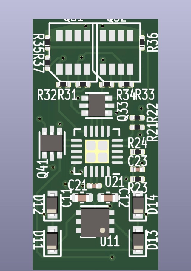
Used for any hard wired N/Z scale application, from locomotives that do not support drop in decoders, to passenger car and caboose lighting operations.
View the schematic: Wired-N-1A-2-1.pdf
Supporting CALCULATIONS.md discussions how component values were determined.
Power from the two rails is fed into a bridge rectifier made up of four discrete diodes D11-D14. As DCC is a square wave, the output is nearly but not quite continuous DC power with low ripple. That power is split off to drive the motor and functions directly, labeled as Vdrive. A linear regulator U11 is used to generate +5v for the micro-processor, and has two support capacitors.
The project requirements for this design are to operate from 6v to 30v of input.
A PIC18F06Q40 processor is used in this design due to it's avaialbility in a 3mm x 3mm VQFN-20 package. PIC processors require minimal support components. C21 is a local bypass capacitor that is placed closed to the power pins. C23 and R11 form a hold up circuit for MCLR which must be kept high during normal operation. If MCLR drops, the chip will reset.
Particular notes on this part:
The H-Bridge controls the current to the motor. It is driven by a PWM signal generated by the micro-controller. The software generates 4 PWM signals, P1A-P1D, which are used to control speed and direction.
The H-bridge is simply 4 high power MOSFETs arranged in an H configuration. This design uses two discrete dual MOSFET chips each with 1 PNP and 1NPN MOSFET, which is a common arrangement. Resistors are placed on the gate inputs to prevent inrush from damaging the micro-controller.
External diodes are omitted on this design to save space, the body diode of the MOSFET must do the job.
In order to calculate BackEMF, a 100nf capacitor C31 is added to reduce signal noise. The resistors R35 and R36 then reduce the voltage to an appropriate level for the analog input of the micro-controller. By monitoring this voltage the micro-controller can calculate the load.
This design supports functions F0F, F0R, F1-F6.
Functions F0F, F0R, and F1-F6 are designed to be connected to external device in a "common anode" configuration.
Vdrive power is provided as a common anode source at both ends of the board. The MOSFET connects to ground when turned on by the micro-processor. A resistor is provided on the gate of each MOSFET to manage inrush current.
MA & MB are the two motor connection solder pads.
RL & RR are the left and right rail solder pads.
F0F, F0R, & F0-F6 are the function solder pads.
CA are the Common Anode solder pads.
MCLR, +5, GND, PGD, PGD make up the ISCP connection points.
| Qty | Value | Footprint | References |
|---|---|---|---|
| 11 | 390R | Resistor_SMD:R_0805_2012Metric | R31, R55, R56, R61, R62, R71, R72, R73, R74, R75, R76 |
| 8 | 3K | Resistor_SMD:R_0805_2012Metric | R59, R81, R82, R83, R84, R85, R86, R87 |
| 8 | White LED | LED_SMD:LED_0805_2012Metric | D61, D62, D81, D82, D83, D84, D85, D86 |
| 7 | BSS138K | Package_TO_SOT_SMD:SOT-23 | Q31, Q71, Q72, Q73, Q74, Q75, Q76 |
| 6 | 10K | Resistor_SMD:R_0805_2012Metric | R21, R32, R51, R52, R53, R54 |
| 6 | 1N5819 | Diode_SMD:D_SOD-323 | D11, D12, D13, D14, D15, D21 |
| 4 | 10uF | Capacitor_SMD:C_0805_2012Metric | C12, C13, C51, C52 |
| 2 | 01x06 | Connector_PinHeader_2.54mm:PinHeader_1x06_P2.54mm_Vertical | J1, J2 |
| 2 | 100nF | Capacitor_SMD:C_0805_2012Metric | C21, C22 |
| 2 | 22K | Resistor_SMD:R_0805_2012Metric | R57, R58 |
| 2 | DTC143ZCA | Package_TO_SOT_SMD:SOT-23 | Q53, Q54 |
| 2 | PMV250EPEA | Package_TO_SOT_SMD:SOT-23 | Q51, Q52 |
| 2 | PMV55ENEAR | Package_TO_SOT_SMD:SOT-23 | Q55, Q56 |
| 1 | 01x02 | Connector_PinHeader_2.54mm:PinHeader_1x02_P2.54mm_Vertical | JP41 |
| 1 | 01x05 | Connector_PinHeader_2.54mm:PinHeader_1x05_P2.54mm_Horizontal | J3 |
| 1 | 01x05S | Connector_PinSocket_2.54mm:PinSocket_1x05_P2.54mm_Horizontal | J5 |
| 1 | 01x07 | Connector_PinHeader_2.54mm:PinHeader_1x07_P2.54mm_Vertical | J4 |
| 1 | 100R | Resistor_SMD:R_2512_6332Metric | R41 |
| 1 | 4R7 | Resistor_SMD:R_0805_2012Metric | R11 |
| 1 | DNP | Capacitor_THT:CP_Radial_D10.0mm_P2.50mm_P5.00mm | C11 |
| 1 | PIC18F16Q40 | Package_SO:SSOP-20_5.3x7.2mm_P0.65mm | U21 |
| 1 | R/G LED | LED_SMD:LED_RGB_1210 | D87 |
| 1 | SE8633X2-HF | Package_TO_SOT_SMD:SOT-23 | U11 |
The 72 most common of 76 parts.
It measures 50.8 × 76.2 mm and has 2 copper layers, 1.6 mm thick.
76 parts, built around the PIC18F16Q40-I/P, SE8633X2-HF, BSS138K and 1N5819WS. The full list of its parts is on this page, with links to each part's symbol and footprint where PCBKit's library has them.
From the bicknell/DCC-Mobile-Decoder repository on GitHub, at the commit this page was made from: the board is hardware/reference/Breadboard-1/Breadboard-1.kicad_pcb and its schematic hardware/decoders/Atlas-N-1A-2-GP40-1/Atlas-N-1A-2-GP40-1.kicad_sch. PCBKit opens the board in the browser, with nothing to install.
Its repository states no licence, so its author keeps all rights: ask bicknell before reusing the design.
bicknell/DCC-Mobile-Decoder
DCC Mobile Decoder Reference Implementation Hardware & Software

bicknell/DCC-Mobile-Decoder
DCC Mobile Decoder Reference Implementation Hardware & Software

bicknell/DCC-Mobile-Decoder
DCC Mobile Decoder Reference Implementation Hardware & Software

bicknell/DCC-Mobile-Decoder
DCC Mobile Decoder Reference Implementation Hardware & Software


msplr/PolyPot
Main repository of the PolyPot semester project - yet another IoT device

Alberto0235/DRSSTC-Fiber-Optic-Interrupter
Custom 4-layer interrupter control board for DRSSTC systems. STM32F405-based, fiber-optically isolated outputs, hardware E-brake safety chain, and controlled-impedance routing (90Ω USB, 50Ω FSMC/SDIO).

henriheimann/prosper3-monitor
Repository of the Prosper III Environment Monitor project ☀️🌱

RedlabsDE/Digital-DC-Load
In the "Calibration" page, the raw ADC values are displayed. The user can set the raw DAC value.
