
2 layers124 × 112 mm

 rassweiler/pi-networked-counter
3d printed counter using Pi5, python, pyqt6, and sqlite that can export to folders or sharepoint
LED Board is an open-source printed circuit board by rassweiler, from the rassweiler/pi-networked-counter repository on GitHub, published under the GPL-3.0 licence. It is a 2-layer board of 55 × 34 mm with 14 parts on 17 nets, routed with 52 tracks and 0 vias.
It is built around the AQY210EH. Its parts include 5 resistors, 4 ICs and 1 connector.
Network attached counter using Pi5, python, pyqt6, and sqlite
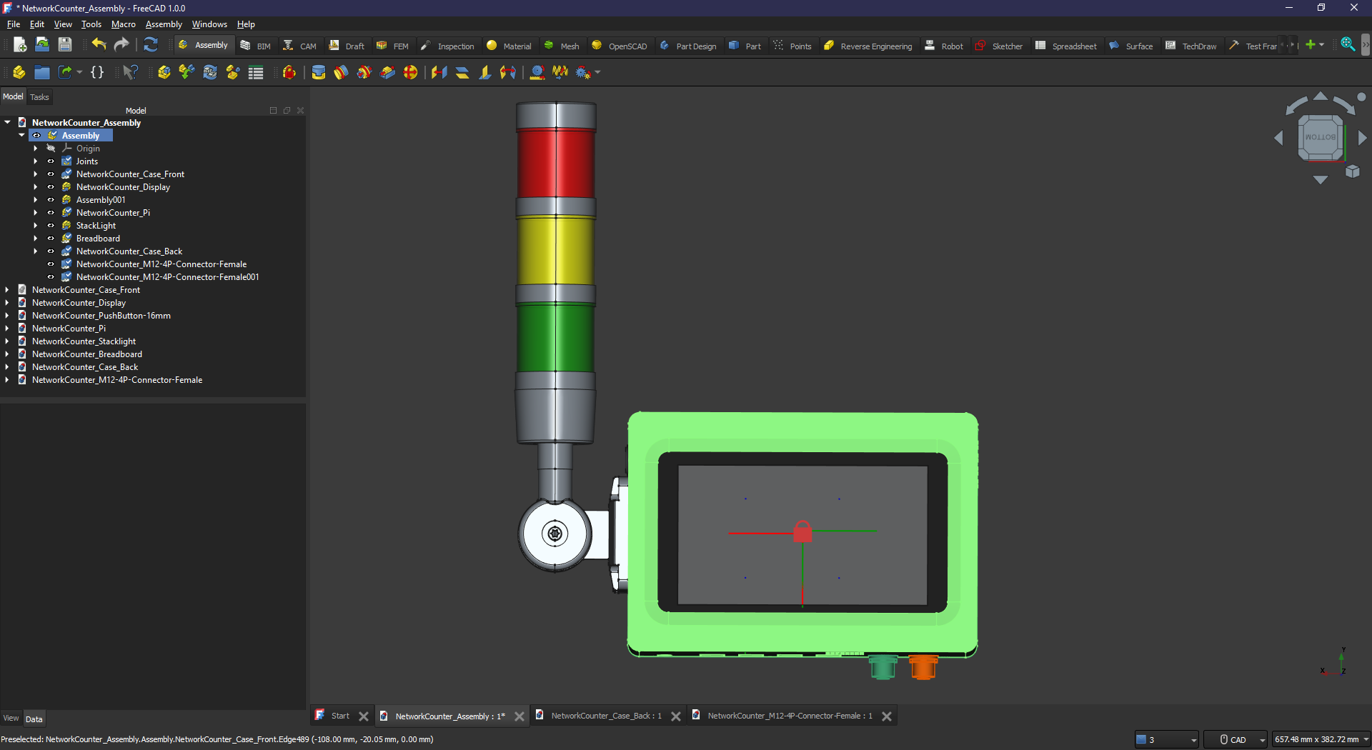
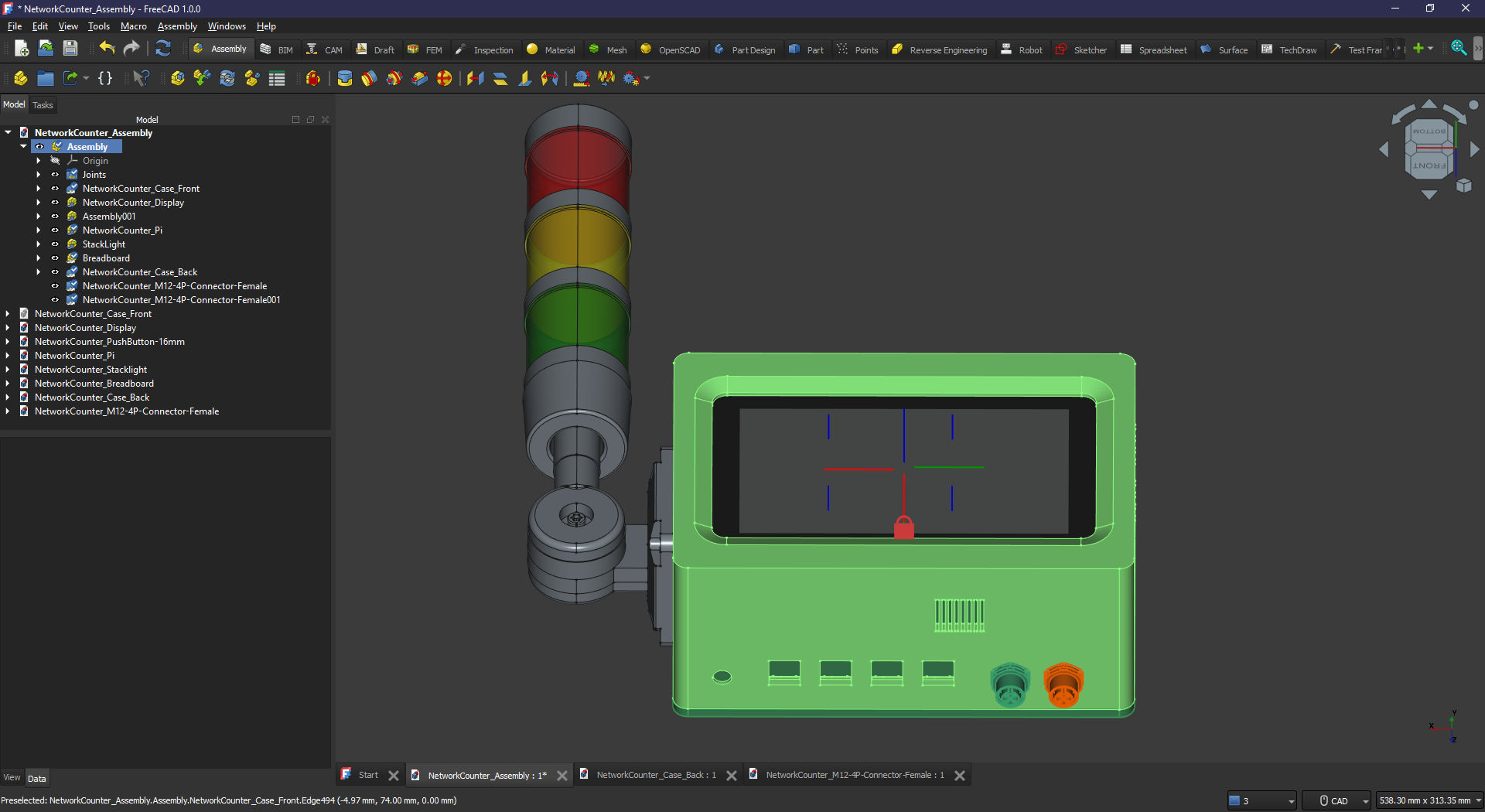
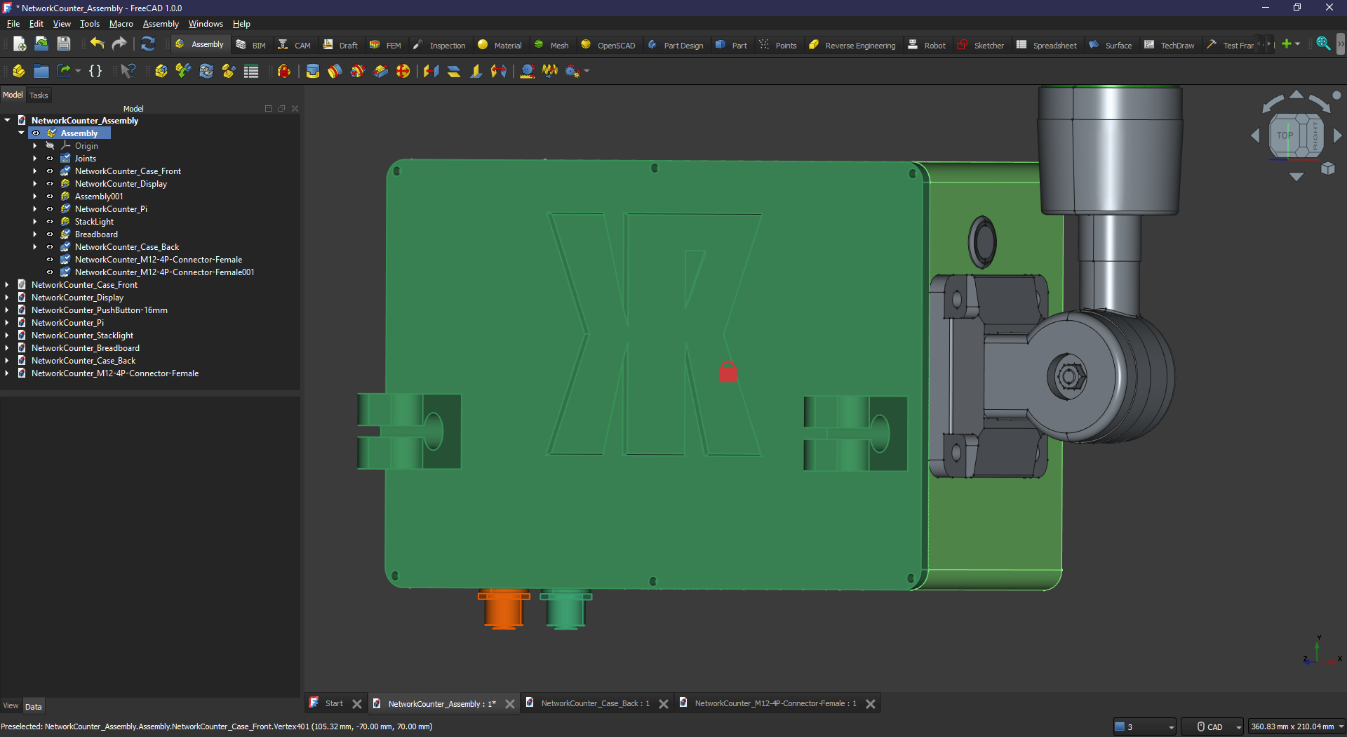
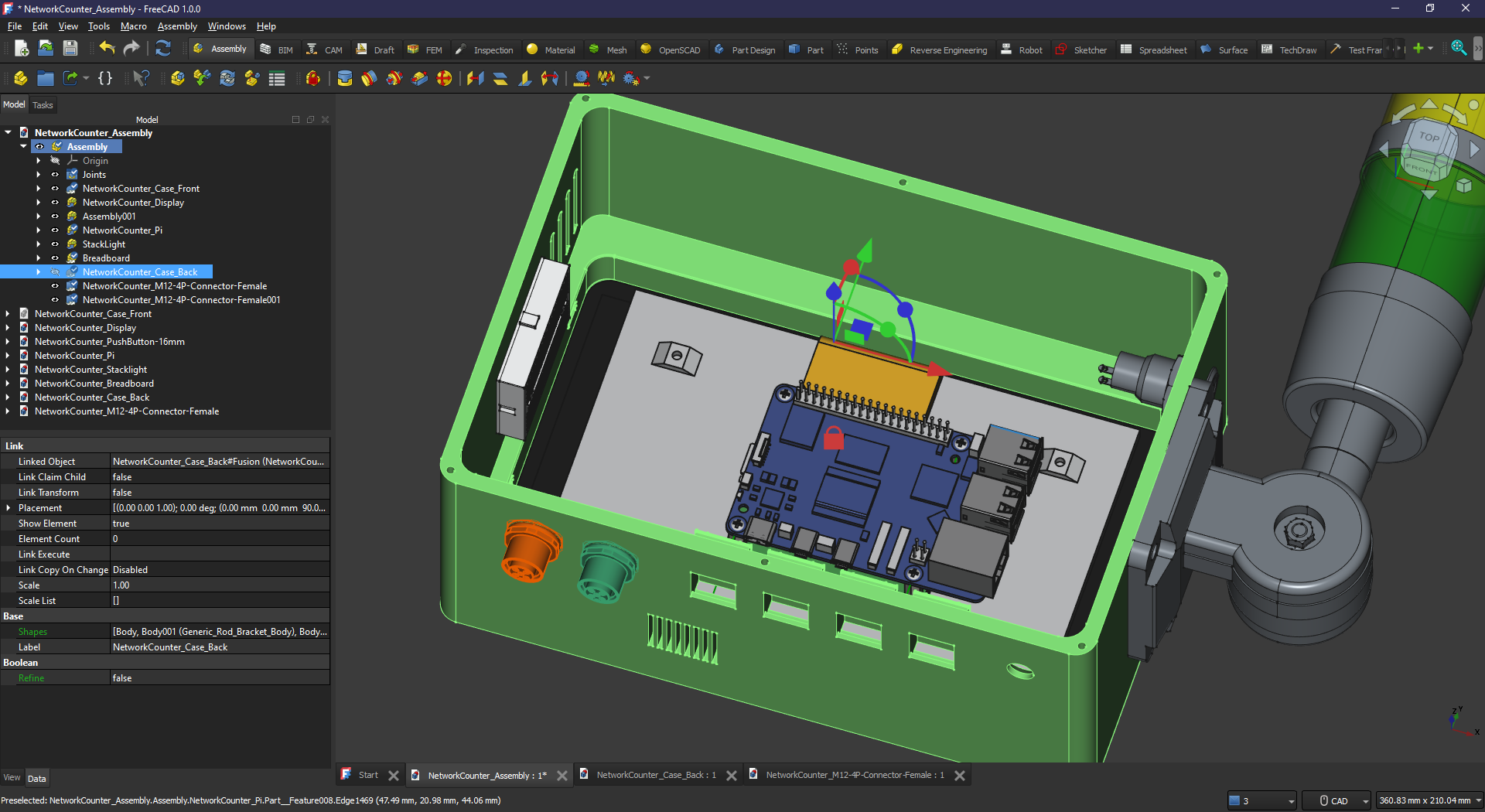


git clone https://github.com/rassweiler/pi-networked-counter.git && cd pi-networked-counterpython3 -m venv venv
source venv/bin/activate
pip3 install gpiozero lgpio msal msal_extensions python-dotenv pygobjectsudo apt install qtcreator sqlitebrowsersudo apt update && sudo apt upgradesudo apt install < .packagessudo nano /etc/sudoers.d/010_pi-nopasswd
remove NOPASSWD:sudo visudo
Insert:
Defaults logfile=/var/log/sudosudo nano /etc/ssh/sshd_config
PermitRootLogin prohibit-password
MaxAuthTries 5
MaxSessions 3
MaxStartups 3:90:15
PasswordAuthentication noecho -e "# Restrict key exchange, cipher, and MAC algorithms, as per sshaudit.com\n# hardening guide.\n KexAlgorithms sntrup761x25519-sha512,sntrup761x25519-sha512@openssh.com,curve25519-sha256,curve25519-sha256@libssh.org,gss-curve25519-sha256-,diffie-hellman-group16-sha512,gss-group16-sha512-,diffie-hellman-group18-sha512,diffie-hellman-group-exchange-sha256\n\nCiphers chacha20-poly1305@openssh.com,aes256-gcm@openssh.com,aes256-ctr,aes192-ctr,aes128-gcm@openssh.com,aes128-ctr\n\nMACs hmac-sha2-256-etm@openssh.com,hmac-sha2-512-etm@openssh.com,umac-128-etm@openssh.com\n\nHostKeyAlgorithms sk-ssh-ed25519-cert-v01@openssh.com,ssh-ed25519-cert-v01@openssh.com,rsa-sha2-512-cert-v01@openssh.com,rsa-sha2-256-cert-v01@openssh.com,sk-ssh-ed25519@openssh.com,ssh-ed25519,rsa-sha2-512,rsa-sha2-256\n\nRequiredRSASize 3072\n\nCASignatureAlgorithms sk-ssh-ed25519@openssh.com,ssh-ed25519,rsa-sha2-512,rsa-sha2-256\n\nGSSAPIKexAlgorithms gss-curve25519-sha256-,gss-group16-sha512-\n\nHostbasedAcceptedAlgorithms sk-ssh-ed25519-cert-v01@openssh.com,ssh-ed25519-cert-v01@openssh.com,sk-ssh-ed25519@openssh.com,ssh-ed25519,rsa-sha2-512-cert-v01@openssh.com,rsa-sha2-512,rsa-sha2-256-cert-v01@openssh.com,rsa-sha2-256\n\nPubkeyAcceptedAlgorithms sk-ssh-ed25519-cert-v01@openssh.com,ssh-ed25519-cert-v01@openssh.com,sk-ssh-ed25519@openssh.com,ssh-ed25519,rsa-sha2-512-cert-v01@openssh.com,rsa-sha2-512,rsa-sha2-256-cert-v01@openssh.com,rsa-sha2-256\n\n" > /etc/ssh/sshd_config.d/ssh-audit_hardening.confsudo systemctl stop avahi-daemon && sudo systemctl disable avahi-daemon
sudo apt purge avahi-daemon -ysudo systemctl stop cups && sudo systemctl disable cups
sudo apt purge cups -y PI configure Set the locale to UTF-8
Setup keyring for sharepoint integration Run seahorse and make sure there is a default keystore
clone repository to PI:
git clone https://github.com/rassweiler/pi-networked-counter.git && cd pi-networked-countersudo cp objectcounter.desktop /etc/xdg/autostart/objectcounter.desktopcp objectcounter.desktop ~/.local/share/applications/Then restart the system to get the app in the menu under other, then right click the app and select add to taskbar
echo "dtoverlay=gpio-poweroff,gpiopin=25,active_low" >> /boot/firmware/config.txt.settup.toml file your sharepoint access details:[sharepoint]
authority = "https://login.microsoftonline.com/{AID}"
client = "{CID}"
scopes = 'User.ReadBasic.All Files.ReadWrite Sites.ReadWrite.All'
endpoint = "https://graph.microsoft.com/v1.0/me" get_token.sh script once to initialise your sharepoint token, it should provide a link and a key to login using a browser.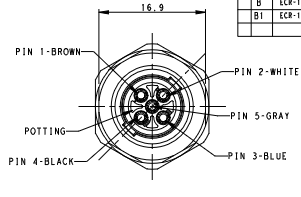
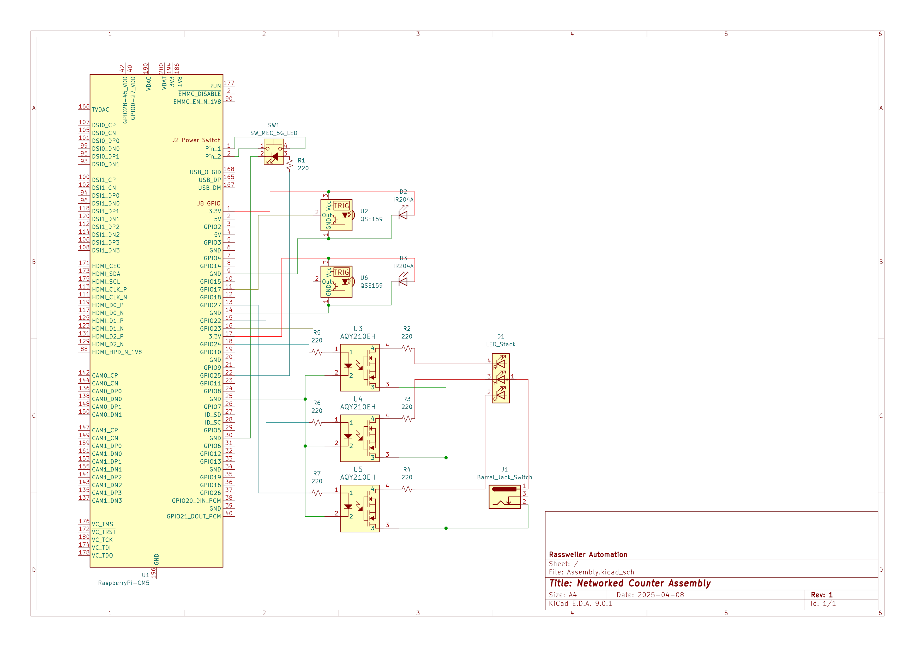
The Pi5 board is not entirely accurate, the J2 and J8 pins are proper however.
| Qty | Value | Footprint | References |
|---|---|---|---|
| 5 | 220 | Resistor_THT:R_Axial_DIN0204_L3.6mm_D1.6mm_P5.08mm_Horizontal | R1, R2, R3, R4, R5 |
| 4 | AQY210EH | Library:Panasonic_AQY210EH | U1, U2, U3, U4 |
| 2 | , | ||
| 2 | MountingHole_3.2mm_M3_DIN965_Pad_TopBottom | MountingHole:MountingHole_3.2mm_M3_DIN965_Pad_TopBottom | Mount, Mount |
| 1 | Conn_01x12_Pin | Connector_PinHeader_2.54mm:PinHeader_1x12_P2.54mm_Vertical | J9 |

biomurph/BioVill_Badge
DEFCON Micro Fluidics Badge Design For Biohacking Village

google/mozc-devices
Circuit diagrams and firmware source code for Gboard DIY keyboards


hackclub/OnBoard
💡 Join 1,000 teenagers and make your first PCB with a $100 grant!


Twotoz/C5VRX
Ultra-minimal, zero-CPU 5.8 GHz analog FPV video receiver using ESP32-C5 Wi-Fi 6 PHY MODEM_DIAG, BitScrambler WBFM demodulation & resistor DAC CVBS
It measures 55 × 34 mm and has 2 copper layers, 1.6 mm thick.
14 parts, built around the AQY210EH. The full list of its parts is on this page, with links to each part's symbol and footprint where PCBKit's library has them.
From the rassweiler/pi-networked-counter repository on GitHub, at the commit this page was made from: the board is Schematics/LED_Board/LED_Board.kicad_pcb and its schematic Schematics/Assembly/Assembly.kicad_sch. PCBKit opens the board in the browser, with nothing to install.
Its repository publishes it under the GPL-3.0 licence: you may reuse it on that licence's terms (keep the author's notice, and for a copyleft licence share your changes alike).